One of the Most popular stepper motor is the 28BYJ-48. After the article that was published in this blog, you should already know everything you need about this type of engine of precision in which you can control the turn so that it advances slowly or stays in a position you want. That allows them to have a multitude of applications, from industrial, to robotics, through many others that you can think of.
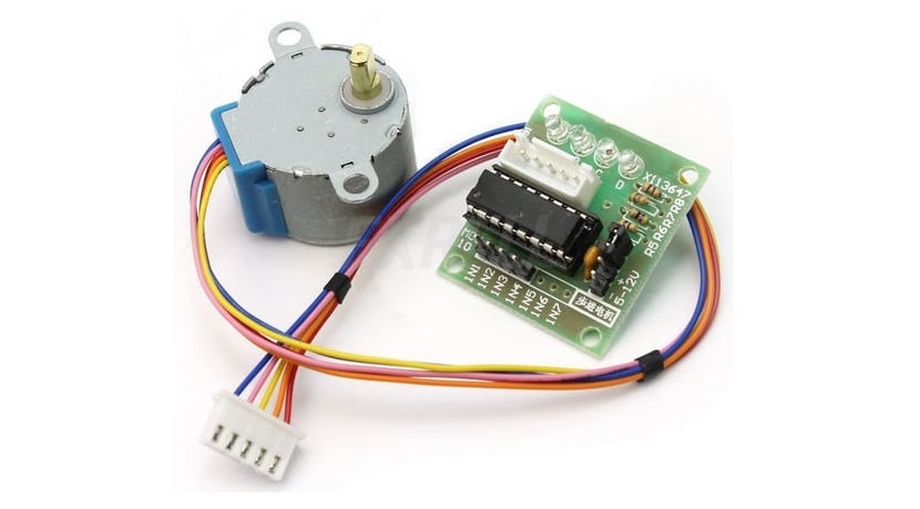
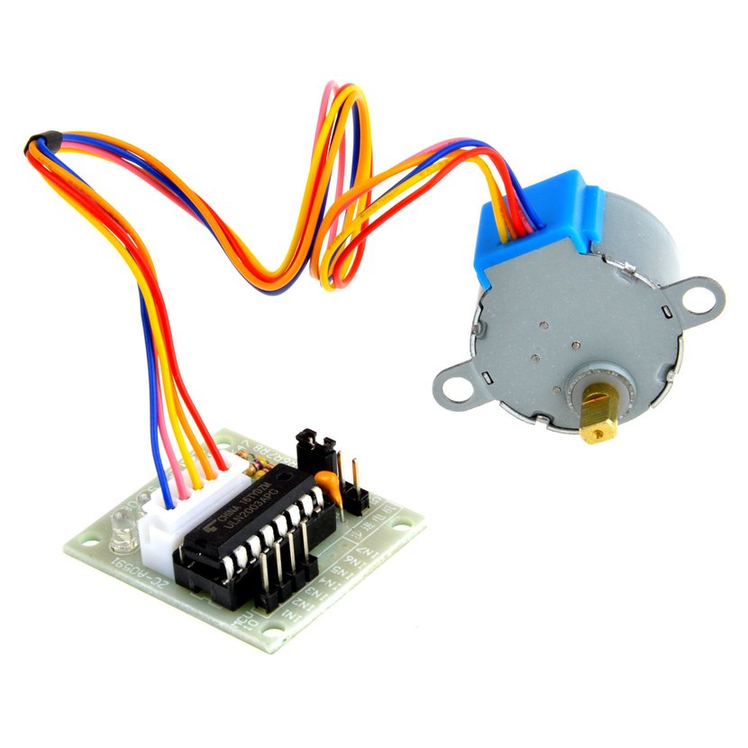
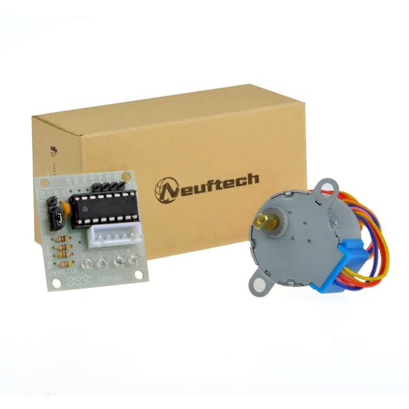
The 28BYJ-48 is a small unipolar type stepper motor, and easy to integrate with Arduino, since it has a driver / controller module model ULN2003A that is usually included with it. All for a very cheap price and a fairly compact size. Those features also make it ideal to start practicing with these devices.
28BYJ-48 Features
And motor 28BYJ-498 It is a stepper motor that has the following characteristics:
- Type: stepper motor or unipolar stepper
- Phases: 4 (full step), as there are 4 coils inside.
- Resistance: 50 Ω.
- Engine torque: 34 N / m, that is, if the Newtons per meter are passed to Kg, it would be a force equivalent to putting about 0.34 Kg per cm on its axis. Enough to lift with a pulley just over a quarter of a kilo.
- Consumer goods: 55mA
- Steps per lap: 8 of the half step type (45º each)
- Integrated gearbox: yes, 1/64, so it divides each step into 64 smaller ones for greater precision, therefore, it reaches 512 steps of 0.7º each. Or it can also be seen as 256 full steps per lap (full step).
Full or half steps, or full and half steps, are the modes in which you can work. If you remember, in the article on stepper motors I said that the code example for Arduino IDE worked at full torque.
For more information, you can download your datasheetas for example this. As for the pinout, you do not have to worry too much, although you can also see information in the datasheet of the model you have purchased. But this concrete has a connection that allows you to connect all the cables at once, without worrying about polarization or where each one goes, just insert into the controller and voila ...
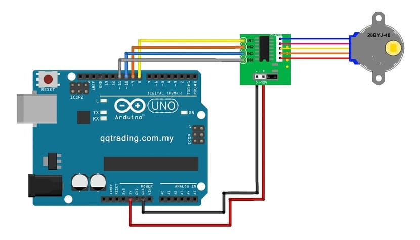
As for the motor controller or driver included in this 28BYJ-48 motor, you have the ULN2003A, one of the most popular and that you can use with Arduino very easily. It has an array of Darlington transistors that supports up to 500mA and has connection pins to link the 4 coils with pins of the Arduino board numbered from IN1 to IN4, as you saw in the stepper motor article that I mentioned earlier. From Arduino, you can have wires from the 5v and GND pin to the two pins on the driver module board marked - + (5-12v) to power the board and the stepper motor.
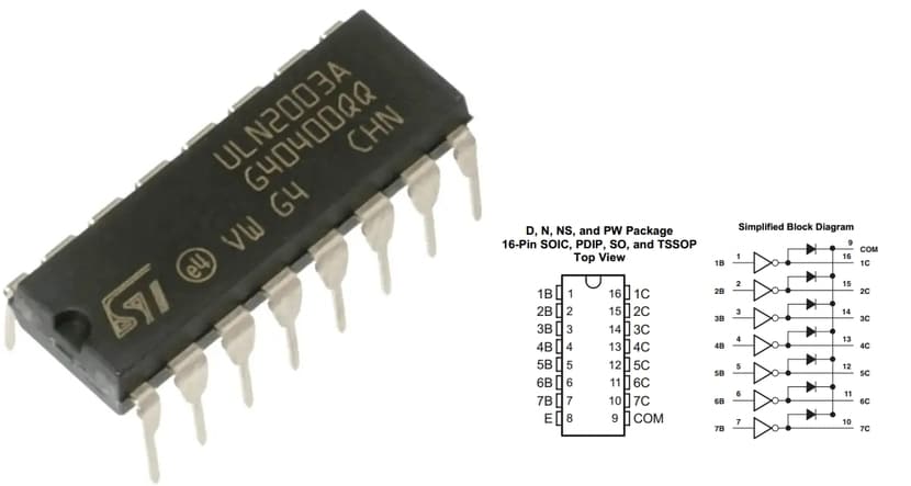
By the way, with the Darlington transistors It is allowed to use a pair of bipolar transistors placed together and acting as a single transistor. This greatly increases the gain of the signal in the resulting single 'transistor', and also allows higher currents and voltages to be carried.
El Darlington pair, as the single "transistor" formed by the combination of two bipolar transistors is known. It originated at Bell Labs in 1952, by Sidney Darlington, hence its name. These transistors are connected in such a way that one NPN has its collector connected to the collector of the second NPN transistor. While the issuer of the first goes to the base of the second. That is, the resulting transistor or pair has three connections as a single transistor. The base of the first transistor and the collector / emitter of the second transistor ...
Where to buy the motor
The you can find in many stores specialized in electronics, and also online like Amazon. For example, you can buy them at:
- For about € 6 you can have a 28BYJ-48 engine with driver module.
- No products found. and cables for its connections, in case you need more than one motor for the robot or project you are doing ...
Programming the 28BYJ-48 with Arduino
First of all, you should be clear about the concepts of a stepper motor, so I recommend you read Hwlibre's article on these items. These motors are not designed to be fed continuously, but to polarize them in their different phases so that they advance only the degrees we want. To excite the phases and control the rotation of the shaft, you will have to feed each connection properly.
The manufacturer recommends driving 2 coils at a time.
- To make it work at maximum torque, with the fastest speed and maximum consumption, you can use this table:
| Step | Coil A | Coil B | Coil C | Coil D |
|---|---|---|---|---|
| 1 | HIGH | HIGH | LOW | LOW |
| 2 | LOW | HIGH | HIGH | LOW |
| 3 | LOW | LOW | HIGH | HIGH |
| 4 | HIGH | LOW | LOW | HIGH |
- To excite only one coil at a time, and make it work in wave drive mode (even for half, but low consumption), you could use the following table:
| Step | Coil A | Coil B | Coil C | Coil D |
|---|---|---|---|---|
| 1 | HIGH | LOW | LOW | LOW |
| 2 | LOW | HIGH | LOW | LOW |
| 3 | LOW | LOW | HIGH | LOW |
| 4 | LOW | LOW | LOW | HIGH |
- Or for advancements half steps, you can use this to achieve greater turning precision in shorter steps:
| Step | Coil A | Coil B | Coil C | Coil D |
|---|---|---|---|---|
| 1 | HIGH | LOW | LOW | LOW |
| 2 | HIGH | HIGH | LOW | LOW |
| 3 | LOW | HIGH | LOW | LOW |
| 4 | LOW | HIGH | HIGH | LOW |
| 5 | LOW | LOW | HIGH | LOW |
| 6 | LOW | LOW | HIGH | HIGH |
| 7 | LOW | LOW | LOW | HIGH |
| 8 | LOW | LOW | LOW | HIGH |
And you may think ... what does this have to do with Arduino programming? Well the truth is that a lot, since you can create a matrix or array with the values in Arduino IDE so that the motor moves at will, and then use said array in a loop or when you need it ... Taking into account that LOW = 0 and HIGH = 1, that is, absence of voltage or high voltage, you can create the signals that Arduino you must send to the controller to drive the motor. For example, to take medium steps you could use the code for the matrix:
int Paso [ 8 ][ 4 ] =
     {  {1, 0, 0, 0},
        {1, 1, 0, 0},
        {0, 1, 0, 0},
        {0, 1, 1, 0},
        {0, 0, 1, 0},
        {0, 0, 1, 1},
        {0, 0, 0, 1},
        {1, 0, 0, 1} };
That is, for the complete code of the sketch From the Arduino IDE, you can use this basic example to test how the 28BYJ-48 stepper motor works. With it, you can rotate the motor shaft once you have the entire diagram properly connected. Try to modify the values or alter the code for the application that you need in your case:
// Definir pines conectados a las bobinas del driver
#define IN1  8
#define IN2  9
#define IN3  10
#define IN4  11

// Secuencia de pasos a par máximo del motor. Realmente es una matriz que representa la tabla del unipolar que he mostrado antes
int paso [4][4] =
{
  {1, 1, 0, 0},
  {0, 1, 1, 0},
  {0, 0, 1, 1},
  {1, 0, 0, 1}
};

void setup()
{
  // Todos los pines se configuran como salida, ya que el motor no enviará señal a Arduino
  pinMode(IN1, OUTPUT);
  pinMode(IN2, OUTPUT);
  pinMode(IN3, OUTPUT);
  pinMode(IN4, OUTPUT);
}

// Bucle para hacerlo girar
void loop()
{
    for (int i = 0; i < 4; i++)
    {
      digitalWrite(IN1, paso[i][0]);
      digitalWrite(IN2, paso[i][1]);
      digitalWrite(IN3, paso[i][2]);
      digitalWrite(IN4, paso[i][3]);
      delay(10);
    }
}
As you can see, in this case it would work with maximum torque activating the coils two by two ...