Like the Ohm's law, Kirchhoff's Laws They are another of the fundamental rules for electronics. These laws allow us to analyze the voltage and current intensity in a node, something essential to know aspects of the circuits.
So if you want know a little more about them, I invite you to continue reading this entire tutorial on fundamental equations and their application in basic circuits ...
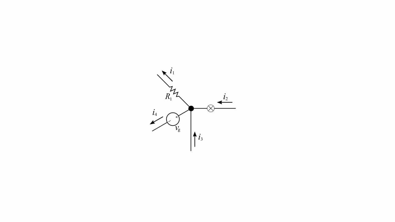
Node, branch, mesh
When you analyze a circuit you can distinguish between the different symbols of the elements, the connecting lines, the connections, and also the nodes. The latter are also called branch or mesh.
Kirchhoff's Laws are used to analyze the electrical properties on these nodes. That is, at the junction points where two or more elements are intertwined. For example, as the point you can see in the main image of this article ...
Kirchhoff's Laws
All the Kirchhoff's laws They are two equalities or equations that are based on the principles of energy conservation and the charging of electrical circuits. Both laws can be obtained directly by deriving the famous Maxwell equations, although Kirchhoff predated this.
Their name come from their discoverer, since they were described for the first time in 1846 by Gustav Kirchhoff. And currently they are widely used in engineering electrical and electronic to know the voltage and current in the circuit nodes, and together with Ohm's Law, they form very effective tools for analysis.
First law or nodes
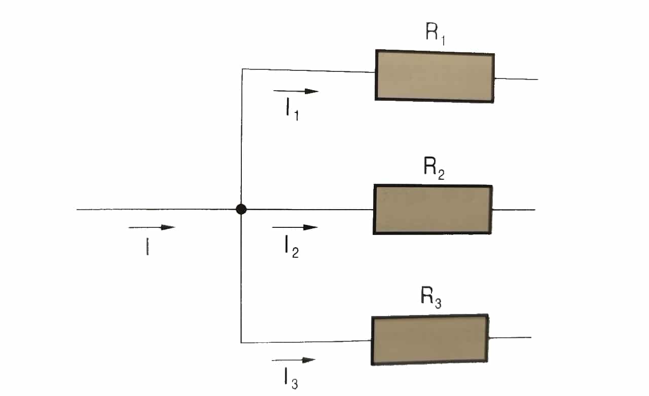
«At any node, the algebraic sum of the intensities entering a node is equal to the algebraic sum of the intensities leaving it. Equivalently, the sum of all currents through the node equals zero.»
I = I1 + I2 + I3 …
Second law or the meshes
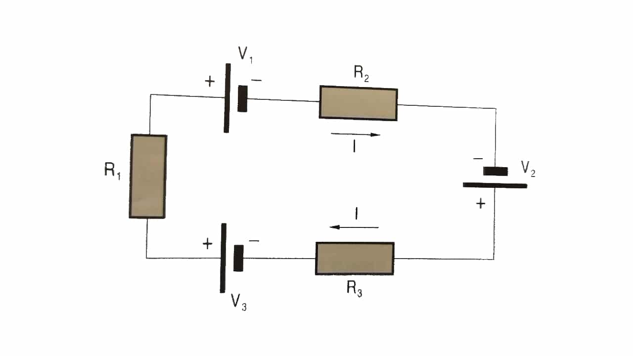
«In a closed circuit, the sum of all voltage drops equals the total supplied voltage. Equivalently, the algebraic sum of the electrical potential differences in a circuit equals zero.«.
-V1 + V2 + V3 = I R1 + I R2 + I R3 = I (R1 + R2 + R3)
Now you can start applying these simple formulas to get the details of current and voltage in your circuits ...