With the digital and analog pins, which you can use on your Arduino board, you can receive or send electrical signals to control or obtain data from your electronic projects. In addition, there are other very interesting signals in this type of plate, and those are the PWM that can emulate an analog signal without actually being analog. That is, they are digital pins that can act in a similar way (not the same) as an analog signal.
These types of signals are very practical for when you not only want to use digital HIGH and LOW signals, that is, 1 or 0, ON and OFF, but you want to go further and describe somewhat more complex signals. For example, it is possible to modulate the speed of a DC motor, or the light intensity of a light, for a solenoid, etc.
Analog vs digital system
Electronic circuits can be divided into two large families or categories: digital and analog. When talking about digital electronics, we are using quantities with discrete values, that is, a binary system represented by electrical signals of a low or high voltage to interpret the state of those bits that are handled. On the other hand, when it comes to an analog circuit, quantities with continuous values are being used.
Within digital systems can be found in turn those of combinational type and those of sequential type. That is, the former are those in which the output of the system only depends on the state of the inputs. On the other hand, in the sequential ones, memory elements are included, and the output will depend on the current state of the inputs and the previous state stored.
In the case of analogs there are not these two large groups or variants, since here they are continuous signals that will always depend on the signal current system. For example, in a loudspeaker, the signal you supply depends on the sound you want to reproduce. The same with a microphone, which will generate an analog signal depending on the sound it is receiving. Surely you have also seen it with many other sensors that we have described in this blog and that act with analog signals (and therefore, a formula had to be created so that later the values could be calculated or conditioned in the Arduino IDE sketches) ...
These characteristics of one and the other make some have their advantages and disadvantages, as is usual in almost everything. For example, digital ones tend to be cheaper, faster, easier to develop, information can be stored more easily, they have greater accuracy, they can be programmed, they are not as vulnerable to the effects of noise, etc. But it is also true that with analogs you can operate with more complex signals.
By example, a digital type Hall effect sensor can only detect the presence or absence of a nearby magnetic field. Instead, an analog Hall effect sensor can do that and also determine the density of said magnetic field thanks to an analog signal that it generates at its output. Knowing how to interpret that signal of greater or lesser voltage well, you can easily know that magnitude. Other examples you have in a multitude of magnitudes of nature that you can measure quantitatively with an analog system, such as temperature, time, pressure, distance, sound, etc.
Analog vs digital signal
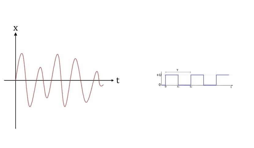
That being said, a analog signal It will be a voltage or electric current that varies with time and continuously. If graphed, the analog signal would be a single frequency sine wave.
With regards to digital signal, is a voltage that varies in a stepwise manner with respect to time. That is, if it is represented on a graph, it will be a step signal that does not vary continuously, but changes in steps or discrete increments.
You should know that there are circuits to go from an analog signal to a digital one or vice versa. These converters they are known as DAC (Digital-to-Analog Converter) and ADC (Analog-to-Digital Converter). And they are very frequent in many devices that we use today, such as TV, computers, etc. With them you can convert the digital signals used by these equipment to an electronic level to work with other peripherals or parts that work in analog.
By example, a speaker or microphone with analog signals that works with a sound card, or digital graphics cards that had the famous RAMDAC chip for the analog monitor ports ... In Arduino this type of converters are also used for multiple projects, as we will see ...
What is PWM?
Although PWM (Pulse-Width Modulation), or pulse width modulation, has a digital base, the shape of its signal resembles a somewhat "square" analog signal. It allows by means of digital pulses to vary the signal to emulate an analog system as I have already commented previously. In fact, if you look at the name, it already gives you clues of what it does, through the width of the digital pulses.
This is beneficial for Arduino since there are many automatisms or electronic components that you can add to your projects and that are not capable of providing a true analog signal, but they use this PWM to operate. Nor can they use a discretized analog signal, that is, that goes to voltage jumps to resemble a digital one. What they can do is use a digital output -Vcc or Vcc of a digital type to generate this peculiar signal ...
Therefore, PWM is a kind of "trick" with which Arduino and other systems can interoperate with this type of signals that they are not quite analogue nor are they conventional digital. To make it possible, they keep a digital output active for a specific time or off, depending on the interest at all times. This is far from what would be a digital clock or binary code signal, whose pulses have the same width.
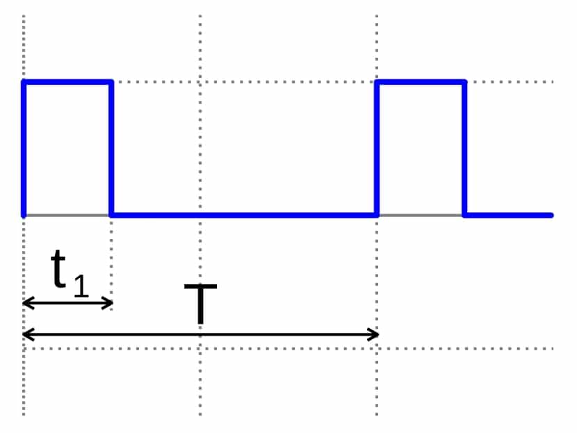
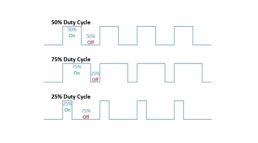
In your projects with Arduino you can check this type of PWM signals in which a constant frequency of pulse triggers is maintained over time, but the width of these pulses is varied. In fact, it is called Duty Cycle when a signal is kept on high with respect to the total of the cycle. Therefore, Duty Cycle is given in%.
Remember that in a PWM you do not work as in an analog signal, between several voltage values and it fluctuates between them. In the case of PWM it is a square signal in the digital style and whose maximum value is Vcc. For example, if you work with a 3V power supply, you can give 3V or 0V pulses, but not 1V or any other intermediate value as would occur in a real analog. What would vary in that case is the pulse width, which we can keep 30% at that high Vcc value, or 60% to give it more power, etc.
But be careful, because if a device supports a Vcc limit and is exceeded with PWM it can be damaged. So it would always be necessary to respect the values of the datasheets provided by the manufacturers. Also, in some devices such as DC motors, relays, electromagnets, etc., a voltage withdrawal after a Duty Cycle can mean that inductive loads can cause damage. That is why the protections timely.
PWM on Arduino
Now that you know how it works, let's see the specific case of PWM within the Arduino world ...
PWM: pinout on Arduino
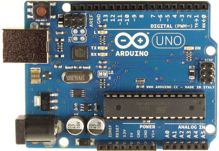
On Arduino boards you can find several pins that implement hardware PWM. You can identify them on the PCB itself because they have a symbol ~ (small head) along with the pin numbering. It could also be done by software in the Arduino code, but that would overload the microcontroller with work, something absurd when it can be done natively and by hardware ...
- Arduino UNO, Mini and Nano- You have 6 8-bit PWM outputs on pins 3, 5, 6, 9, 10, and 11, which will have that ~ right in front of the number.
- Arduino Mega- On this most powerful Arduino board you have 15 8-bit PWM outputs. They are on pins 2 through 13 and 44 through 46.
- Arduino Due: in this case there are 13 8-bit PWM outputs. They are on pins 2 to 13, plus two other analog outputs discretized by DAC with 12-bit resolution.
When you talk about a resolution of 8 bits or 12 bits, etc., in this type of PWM outputs, you are referring to the room for maneuver you have. With 8 bits have 256 levels Between which you can vary, and the 12 bits go up to 4096 levels.
Control with Timers
For hardware PWM control, Arduino will use the timers for it. Each present Timer can serve 2 or 3 PWM outputs. A comparison register for each output complements this system so that when the time reaches the value of the register, the state or value of the output is changed to stop those Duty Cycles. Although there are two outputs controlled by the same Timer, both can have different Duty Cycles, although they share the same frequency.
In the case of the Timers associated with each PWM pin, it will vary depending on the type of Arduino board that you have:
- Arduino UNO, Mini and Nano:
- Timer0 - 5 and 6
- Timer1 - 9 and 10
- Timer2 - 3 and 11
- Arduino Mega:
- Timer0 - 4 and 13
- Timer1 - 11 and 12
- Timer2 - 9 and 10
- Timer3 - 2, 3 and 5
- Timer4 - 6, 7 and 8
- Timer5 - 44, 45 and 46
The prescaled register will divide the time by an integer and the Timer does the rest to control each of the associated PWM outputs. Modifying the registry value can alter the frequency. The frequency They will also be different depending on the Timer and the plate:
- Arduino UNO, Mini and Nano:
- Timer0: allows prescaling of 1, 8, 64, 256 and 1024. The frequency is 62.5 Khz.
- Timer1: with presets of 1, 8, 64, 256 and 1024. With a frequency of 31.25 Khz.
- Timer2: equal to Timer1, only it adds a prescaling of 32 and 128 in addition to the previous ones.
- Arduino Mega:
- Timer0, 1, 2: same as above.
- Timer3, 4, and 5: with frequency of 31.25 Khz and prescaled of 1, 8, 64, 256 and 1024.
Incompatibilities and conflicts
The Timer associated with the outputs is not only for that function, is also used by others. Therefore, if they are being used by another function, you must choose between one or the other, you cannot be using both at the same time. For example, these are some of the incompatibilities that you can find in your projects:
- Servo library: When you use servo motors, Timers are used intensively, which could lead to conflicts. Specifically use Timer1 for UNO, Nano and Mini, that is, you cannot use pins 9 and 10 while you are using a sketch with that library. In Mega it will depend on the number of servos ...
- SPI: If SPI communication is used on the Arduino board, pin 11 is being used for the MOSI function. That is why that PWM pin cannot be used.
- Tone: this function uses Timer2 to operate. So if it is used, you are making pins 3 and 11 (or 9 and 10 for Mega) useless.
Hands-on test with Arduino
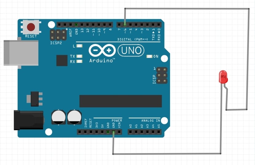
If you want to see on-site how PWM works on Arduino, the best thing you can do is connect the measurement leads of a voltmeter or multimeter (in function to measure voltage) between the PWM pin that you have chosen to use and the ground pin or GND of the Arduino board. In this way, on the screen of the measuring device you will be able to see how the voltage is changing with an output that is digital thanks to this PWM trick.
You can replace the voltmeter / multimeter with an LED to see how the intensity of the light varies, with a DC motor, or with any other element that you want. I have simplified it in the diagram with Fritzing with an LED without more, but know that it can also represent the tips of a multimeter ...
If you use an LED, remember the resistance at the cathode and GND.
For the source code To control the Arduino board microcontroller to make everything work, you should insert this into Arduino IDE (in this case I have used PWM pin 6 of Arduino UNO):
const int analogOutPin = 6;
byte outputValue = 0;

void setup()
{
   Serial.begin(9600);
   pinMode(ledPIN , OUTPUT);

   bitSet(DDRB, 5);       // LED o voltímetro
   bitSet(PCICR, PCIE0);
   bitSet(PCMSK0, PCINT3);
}

void loop()
{
   if (Serial.available()>0)
   {
      if(outputValue >= '0' && outputValue <= '9')
      {
         outputValue = Serial.read();   // Leemos la opción
         outputValue -= '0';      // Restamos '0' para convertir a un número
         outputValue *= 25;      // Multiplicamos x25 para pasar a una escala 0 a 250
         analogWrite(ledPIN , outputValue);
      }
   }
}

ISR(PCINT0_vect)
{
   if(bitRead(PINB, 3))
   {
      bitSet(PORTB, 5);   // LED on
   }
   else
   {
      bitClear(PORTB, 5); // LED off
   }
}
Hello good day. First of all I want to thank you for the time dedicated to this explanation for the newest.
I would like to make you a query. I am trying to run the code on a proteus 8 emulator for Arguino Mega. I connect a voltmeter to pin 6, Proteus is connected to a serial port, but I don't know how or what to vary so that different voltages are output. I had to make minor adjustments to the code to make it compile. Thank you very much for your help