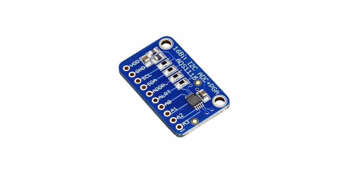
For those projects where an analog to digital signal conversion is necessary, and the microcontroller used does not have this capacity, it is interesting to have this type of ADS1115 module, which provides that ADC conversion capability with 16-bit precision.
Furthermore, this electronic component it may also be interesting to extend the conversion capabilitiesEven if the microcontroller you are using for your project has this capability but you need something else.
A / D and D / A converters
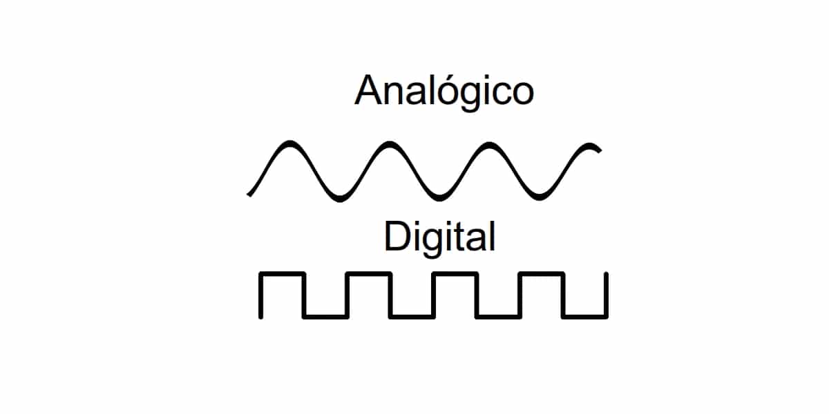
There are two types of signal converters fundamental, although there are also other chips capable of doing both types of conversion at the same time. These are:
- CAD (Analog to Digital Converter) or ADC (Analog-to-Digital Converter): is a type of device that converts the analog signal into a digital signal. To do this, you can use a binary code that encodes the analog signal. For example, associating a binary value with a specific voltage or current value. For example, with 4-bit resolution it can go from 0000 to 1111, and it could correspond to 0v and 12v respectively. Although if a sign bit is used, negative and positive values can be measured.
- CDA (Digital to Analog Converter) or DAC (Digital-to-Analog Converter): it is a device that does the opposite of the above, that is, it transforms binary data into an analog current or voltage signal.
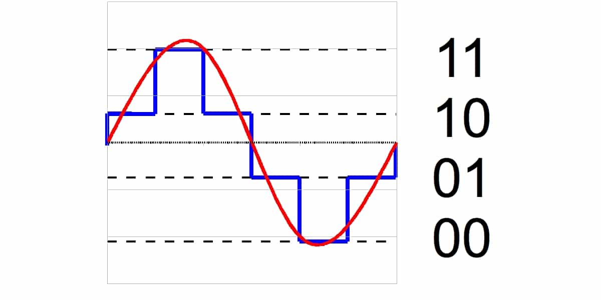
With these converters it is possible to pass from one type of signal to another, as you will see in the case of ADS1115, which would correspond to the first case.
About the ADS1115
The ADS1115 is a signal converter module. What it does is convert from analog to digital. You may think that the Arduino development board itself already includes internal ADCs to be able to do this task when using the analog inputs and that they can be compatible with the microcontroller signals.
Yes, that's right, they have 6 10-bit resolution ADCs in the UNO, Mini and Nano. But with the ADS1115 you add another with a 16-bit resolution, superior to the Arduino, in addition to being able to free the Arduino case. Fifteen of them are for the measurement and a last bit for the sign of the analog signal, since as you know, the analog signal can be negative or positive.
In addition, this module provides everything you need, so that its use is very simple. To connect it to your Arduino you can use the I2CTherefore it's really simple. It even includes a pin marked ADDR with which you can select one of the 4 addresses available for this component.
On the other hand, you have to understand that the ADS1115 has two measurement modes, one is the differential and another the single ended:
- Differential: it uses two ADCs for each measurement, reducing the number of channels to 2, but it provides a clear advantage, which is that it can measure negative voltages and is not as vulnerable to noise.
- single ended: it has four channels by not using both as in the previous case. Each of the 15-bit channels.
In addition to these modes, it includes a comparator mode in which an alert is generated through the ALRT pin when any of the channels exceeds a threshold value that can be configured in the source code of the sketch.
If you want to do measurements less than 5v, but with higher precisions, you should know that the ADS1115 has a PGA that can adjust the voltage gain from 6.144v to 0.256v. Always bearing in mind that the maximum voltage that can be measured in any case will be the power supply voltage used (5v).
Pinout and datasheet
If you want to see all the technical details of the ADS1115 to know its limits at an electronic level or the conditions under which it can operate according to the manufacturer's recommendations, you can use the datasheets that you can find on the net. For example, you can download this from TI (TexasInstruments).
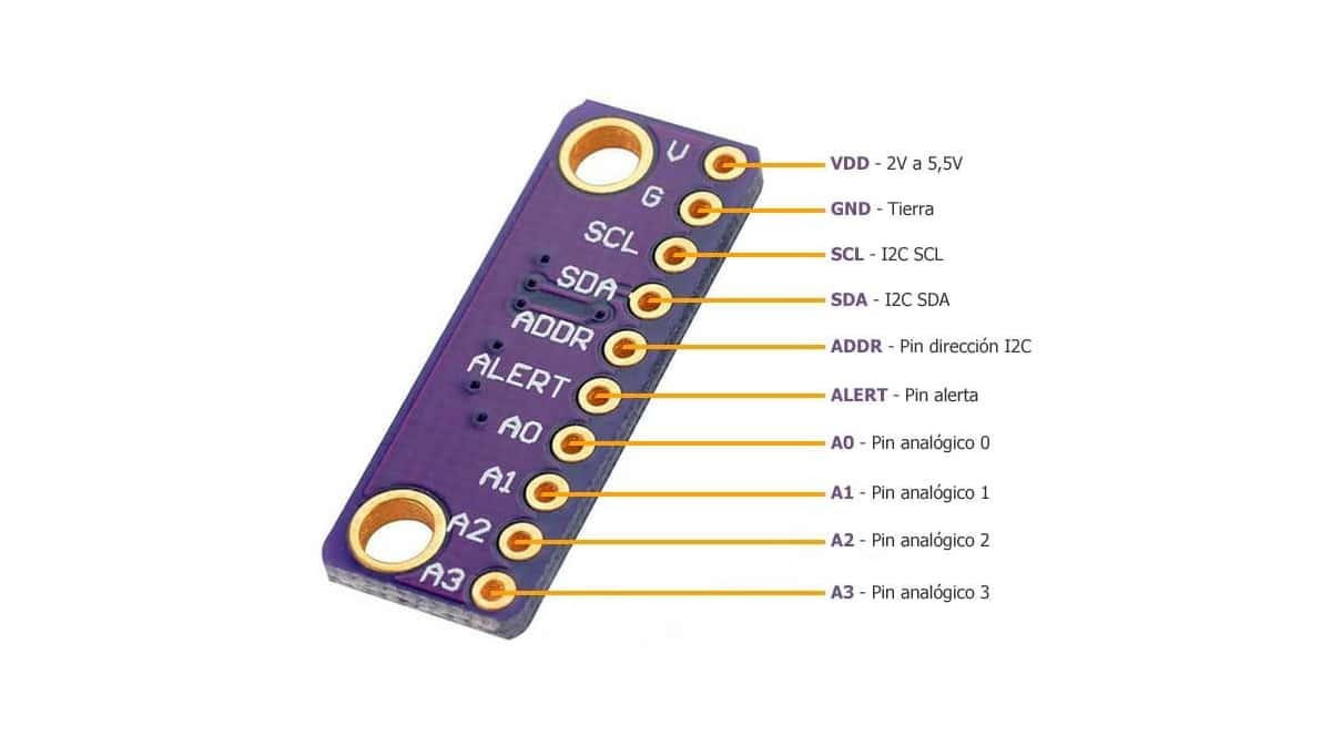
For the pinout and connected, previously I have already commented something about the ALRT signal that also includes about ADDR. But it has other pins that you should also know for a correct integration with your Arduino board or for any other case. The pins available on the ADS1115 module are:
- VDD: supply with 2v to 5.5v. You can power it by connecting it to 5v from your Arduino board.
- GND: ground that you can connect to GND of your Arduino board.
- SCL and SDA: communication pins for the I2C. In this case they must go to the appropriate pins according to your arduino model.
- ADDR: pin for the address. By default it connects to GND, which gives the address 0x48, but you can choose other addresses:
- Connected to GND = 0x48
- Connected to VDD = 0x49
- Connected to SDA = 0x4A
- Connected to SCL = 0x4B
- ALRT: alert pin
- A0 to A3: analog pins
If you want to use single ended You can connect the analog current or voltage you want to measure between GND and one of the 4 available analog pins.
for the connection single ended, we simply connect the load to be measured between GND and one of the 4 available pins. For differential mode you can connect the load to be measured between A0 and A1 or between A2 and A3, depending on the channel you want to use.
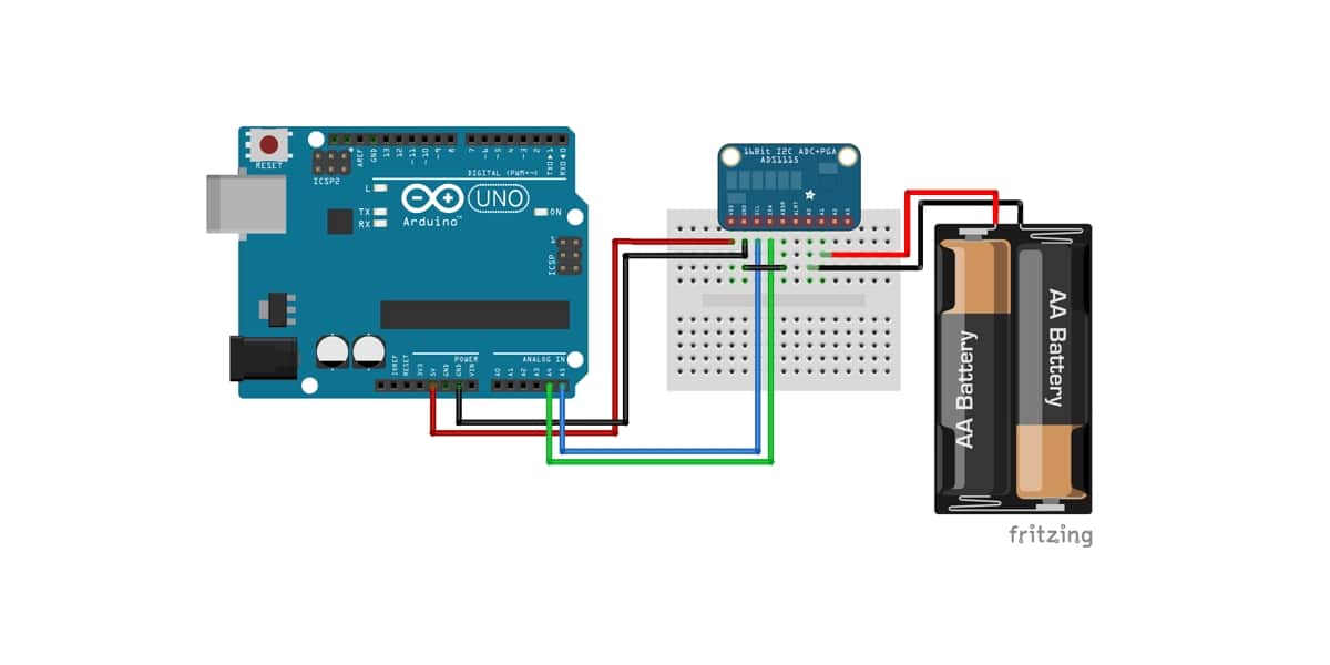
As an example of connection in the case of a differential reading mode, you can see the above image. In it 1.5 batteries are used in series, adding 3v that are connected between A0 and A1 in this case so that the Arduino board can measure the voltage values obtained at each moment through the I2C. Obviously, you can use any other signal to measure, in this case they are batteries, but it can be whatever you want ...
Where to buy the ADS1115?

If you would like to buy the ADS1115You should know that you have modules prepared to integrate with Arduino for quite cheap prices. You can find them in a multitude of specialized electronics stores, as well as on eBay, Aliexpress and Amazon. For example:
Integration with Arduino
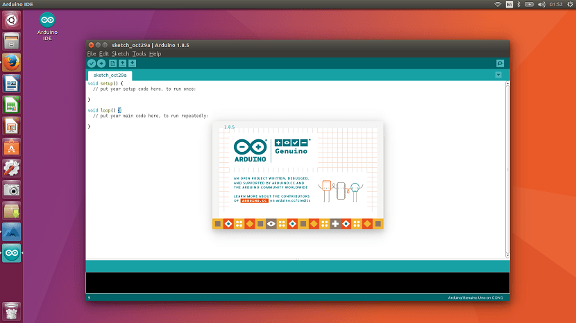
To get started, the first thing is install library corresponding in your Arduino IDE. For this, you can use the most famous, that of Adafruit. To do this, you can follow these steps:
- Open Arduino IDE
- Go to the Sketch menu
- Then to Include Library
- Manage libraries
- In the search engine you can search for Adafruit ADS1X15
- Click on Install
Now you are ready to start, you can access the code of the installed library or the examples available in:
- Open Arduino IDE
- Go to File
- Examples
- And in the list look for the ones in this library ...
Among the examples you will see both for the comparator mode, differential mode and single end mode. You can see the examples to start using them and modify them according to your needs or write more complex code. For more information, I advise you our free introductory course in PDF.
In differential mode can I use it to measure between + 5V and - 5V?