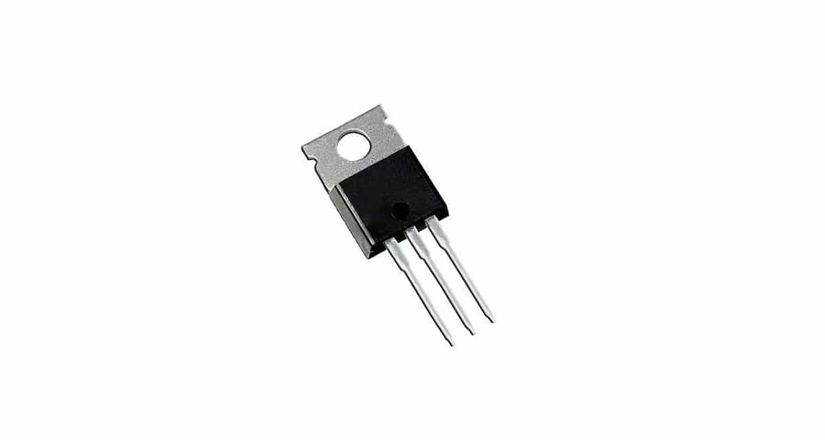
Some time ago we published a tutorial on how you could check capacitors. Now it's the turn of another essential electronic component, how is this. Here you can see how check a transistor explained very simply and step by step, and you can do it with tools as conventional as a multimeter.
The transistors are widely used in a multitude of electronic and electrical circuits for control with this solid state device. Therefore, given how frequent they are, you will surely come across cases in which you have to check them ...
What I need?
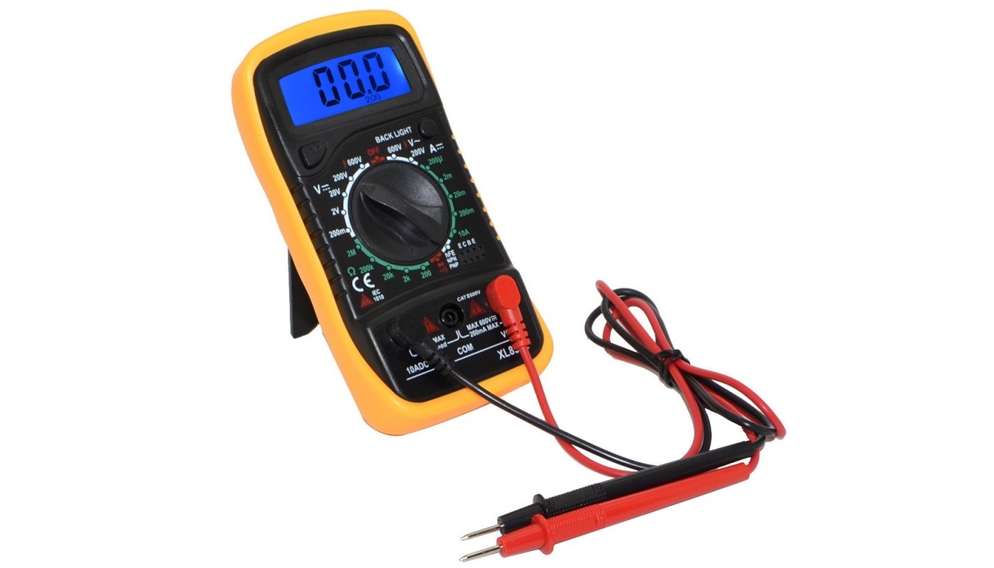
If you already have a good multimeter, or multimeter, that's all you need to test your transistor. Yes, this multimeter it has to have function to test transistors. Many of today's digital multimeters have this feature, even cheap ones. With it you can measure NPN or PNP bipolar transistors to determine if they are defective.
If that is your case, you will only have to insert the three pins of the transistor in the socket of the multimeter that is indicated for it, and position the selector on the hFE position to measure the gain. So you can get a reading and check a datasheet if it corresponds to what it should give.
Steps to check a bipolar transistor
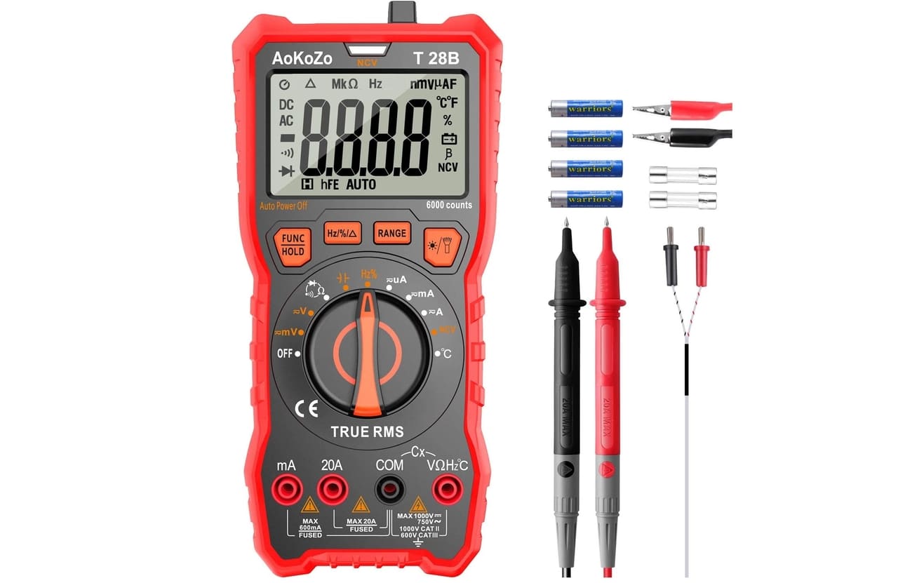
Unfortunately, not all multimeters have that simple feature, and to test it in a more manual way with any multimeter you will have to do it differently, with the «Diode» test function.
- The first thing is to remove the transistor from the circuit to get a better reading. If it is a component not yet soldered, you can save this step.
- Test Base to Issuer:
- Connect the positive (red) lead of the multimeter to the base (B) of the transistor, and the negative (black) lead to the emitter (E) of the transistor.
- If it is a NPN transistor in good condition, the meter should show a voltage drop between 0.45V and 0.9V.
- In the case of a PNP, the initials OL (Over Limit) should be seen on the screen.
- Test Base to Collector:
- Connect the positive lead from the multimeter to the base (B), and the negative lead to the collector (C) of the transistor.
- If it is a NPN in good condition, it will show a voltage drop between 0.45v and 0.9V.
- In case of being a PNP, then OL will appear again.
- Test Issuer to Base:
- Connect the positive wire to the emitter (E) and the negative wire to the base (B).
- If it is an NPN in perfect condition it will show OL this time.
- In the case of the PNP, a drop of 0.45v and 0.9V would be shown.
- Test Collector to Base:
- Connect the positive of the multimeter to the collector (C) and the negative to the base (B) of the transistor.
- If it is an NPN, it should appear on the OL screen to indicate that it is okay.
- In case of a PNP, the drop should again be 0.45V and 0.9V if okay.
- Test Collector to Emitter:
- Connect the red wire to the collector (C) and the black wire to the emitter (E).
- Whether it is NPN or PNP in perfect condition, it would show OL on the screen.
- If you reverse the wires, the positive at the emitter and the negative at the collector, both at the PNP and NPN, it should also read OL.
Any different measurement of that, if done correctly, will indicate that the transistor is bad. You also have to take into account something else, and that is that these tests only detect if the transistor has a short circuit or they are open, but not other problems. Therefore, even if it passes them, the transistor may have some other problem that prevents its correct operation.
FET transistor
In the case of being a FET transistor, and not a bipolar one, then you should follow these other steps with your digital or analog multimeter:
- Put your multimeter in the diode test function, as before. Then place the black (-) probe on the Drain terminal, and the red (+) probe on the Source terminal. The result should be a reading of 513mv or similar, depending on the type of FET. If the reading is not obtained, it will be open and if it is very low it will be short-circuited.
- Without removing the black tip from the drain, place the red tip on the Gate terminal. Now the test should not return any reading. If it shows any results on the screen, then there will be a leak or short circuit.
- Put the tip in the fountain, and the black one will remain in the drain. This will test the Drain-Source junction by activating it and obtaining a low reading of about 0.82v. To deactivate the transistor, its three terminals (DGS) must be short-circuited, and it will return from the on state to the idle state.
With this, you could test FET-type transistors, like MOSFETs. Remember to have the technical characteristics or data sheets of these to know if the values you obtain are adequate, since it varies according to the type of transistor ...
Excellent explanation. I wish my electronics teachers had explained it like that
Thank you very much