
Today we return with one of our interesting tutorials. This time I want to show you a very simple project that will take you a short time to implement and with which you will literally be able to build a kind of translator from a language written to Morse code. As is usual, the truth is that we will not go beyond a project where a breadboard plate and a arduino board Since, in case you want to go further, both at the software level and in terms of final project completions, you should be the one to implement a solution, the less, more attractive.
The idea starts from creating a Translator of any type of font, words or phrase to morse code. This is as simple as using an Arduino board that will be the one that has the necessary software loaded so that, through its outputs, we can make a few LEDs look according to the meaning in Morse language that we are expressing. To easily write the text we want to translate, we will use a mobile phone equipped with an Android operating system that will send the text through a bluetooth connection to our board. Arduino UNO.
Material needed to carry out the project
As we have more or less tried to indicate in the upper lines, to carry out this project we will need specific material although, if you like the world maker, I am sure that either it will not be difficult for you to find what you are missing in any of your most frequent stores in case you do not have it although, as I say, they are usually fairly frequently used items. Specifically, we will need to have the following list:
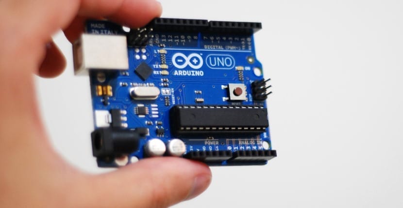
- Ardunio ONE
- Protoboard
- Bluetooth for Arduino
- Four LED lights, 3 of the same color and a fourth light of a different color
- Several cables to facilitate the connection between devices, in this case to connect the breadboard and our Arduino controller
- Cable to connect the Ardunio to a USB input in order to download the software
- Talking horn
- Computer with the Arduino IDE installed correctly and USB connection to connect the board
- Mobile device with operating system Android 2.2.1 or higher
Once we have all the necessary elements available, we can continue with the execution of the project. One point to keep in mind is that literally it is not necessary to have the bluetooth adapter used in this project or a card Arduino UNO as such since any other with the basic connections can be used, we will only have to pay attention to the connections used so that, for example, in the case that digital output 13 of our Arduino UNO this corresponds to the same output of the board you are using.
Steps to carry out the project
To carry out this project, below, I will indicate a series of steps related to the assembly and connection of all the elements that make up the previous list that we must follow for their correct execution. As is often the case in this type of project, feel completely free to modify any line of code or add hardware to evolve and even perfect its operation since any type of improvement is always welcome.
In the first place we will carry out the connection of Arduino UNO with our breadboard. Specifically, the outputs used will be GND and 3.3 V. These same lines will serve us, among other things, to provide power to our Bluetooth adapter.
Once we have made these connections, it is time to coordinate the data input and output of the bluetooth adapter with the digital data inputs and outputs of the Arduino board. In this way we will have our adapter perfectly connected to the card both so that it receives current and so that it is completely available at a technical level to be able to start 'listen'the data that reaches it through the ports of entry of the Arduino UNO. As a detail, tell you that on certain occasions, due to both the card that we use and the bluetooth adapter, the connections used may vary so, at this point, the best thing is look at the adapter installation documents as they are usually accompanied by connection diagrams.
We arrive at 3 volt horn connection. For this we will use digital output number 13 of Arduino UNO. The remaining connection, as usual, we must connect it to GND or ground so that the operation of the horn is correct.
Now comes the time connect the different LEDs. In order not to try to get confused, tell you that the idea is to connect the longest leg of it, positive, to one of the digital outputs of Arduino UNO while the shorter one connects directly to GND or ground. In this way we would find that the first of the green LEDs would be connected to digital output 12, the next to output 8, the third green LED to output 7 while the only blue LED would be connected to the output digital 4.
The last step, once we have all the wiring ready is use the USB connection cable to connect our Arduino UNO to the computer and thus be able to equip it with the necessary software, which we will write and compile from the Arduino IDE itself.
Connection between the Arduino board and the computer
One point that must be taken into account when we have the board connected to the computer to know that everything works correctly, at least in principle, is that the board will have a green light on at all times as long as it remains connected to the computer. On the other hand and depending on the Bluetooth adapter that we use, this usually has a red light flashing due to a connection not being established with the Android device that we will use to send the letters, phrases or words to the plate.
I know that the above detail may seem like something very 'silly'but I can assure you that they are very valid, necessary and especially interesting indications if we take into account that within the maker community they may exist people who are starting and that, thanks to these little ones'Tricks'they can understand that, at least, the current reaches both the adapter and the board itself.
At this point we just have to download the application MORSE.apk attached. This application must be installed on your mobile device equipped with the Android operating system. Once it has been installed, you just have to open the application and press continue. This time the option that interests us the most is'Send Text', same on which we have to click to access it. Once inside we must click on 'Connect' to establish the connection with our plate.
The encoding process that has been followed is as follows.
- Once you access the application on your Android device and follow the previous steps, you will be able to write any letter, word or phrase. Once you have written what you want, you just have to click on send.
- If the text has been received correctly the system will automatically turn on the lights and emit a sound
- The idea is that the first green light will go on and off to determine the 'point'. In turn, the horn will sound and turn off at the same time.
- The second and third green lights will turn on and off to determine the 'line' in turn. The horn, as in the previous case, will turn on and off at the same time.
- Finally the fourth light, that is, the blue light, will turn on and off to determine the end of the character, word or phrase. When there is some type of space between each character, word or phrase this light will turn on and off twice.
As points to take into account, just tell you that in this case the Android application has been made thanks to App Inventor, a very simple way to generate the code and design of an application that will later be run on a device equipped with the operating system created by Google engineers.
More information and details: instructables