Coils and op amps allow you to create very interesting circuits, such as the famous frequency filters. These filters have a multitude of applications in the electronics industry. As is the case with the low pass filter, the high pass filter, etc. They are especially interesting for certain sound applications, being able to filter noises, or more or less serious sounds according to their frequency. Therefore, they are very useful.
If you want to know more about him low pass filter, and other filters, and how they can help you in your projects with Arduino or DIY, I encourage you to continue reading ...
Electric filters
As its name suggests, a filter is a circuit that is made up of a series of coils and capacitors, and even some operational amplifiers, for the purpose of letting only certain parts of a frequency pass. That is, of the entire spectrum of available frequencies, they will filter one or more parts to prevent them from passing through.
Yes for example We are talking about the spectrum audible by the human being, which goes from 20 Hz to 20 Khz, with filters you could eliminate the lowest, or the highest, in order to only allow the more or less treble / bass sounds to pass. It is something that many audio recording or reproduction systems use, such as microphones, speakers, etc.
PREMIUM QUALITY
-

- Low pass filter
-

- High pass filter

-

- Frequency filter graphs
According to filter type, or rather, depending on the frequency they block or the one they let through, there are different types of circuits that are:
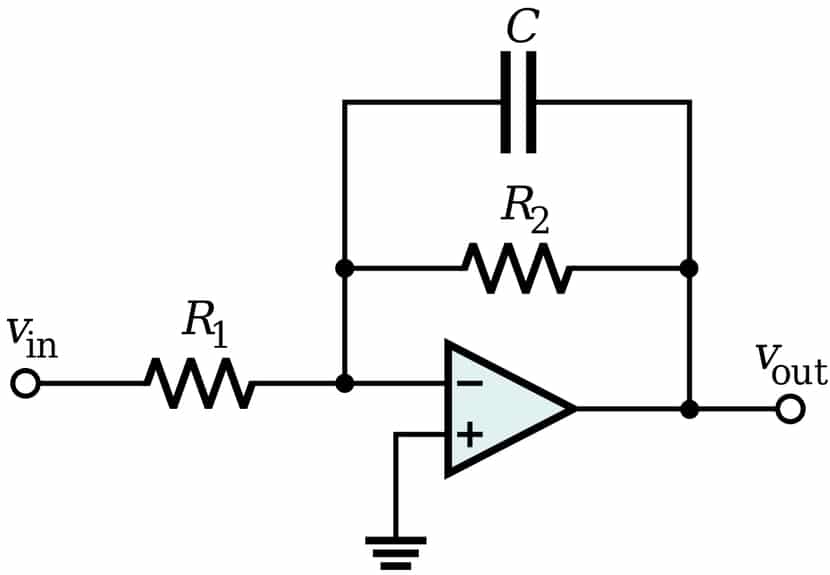
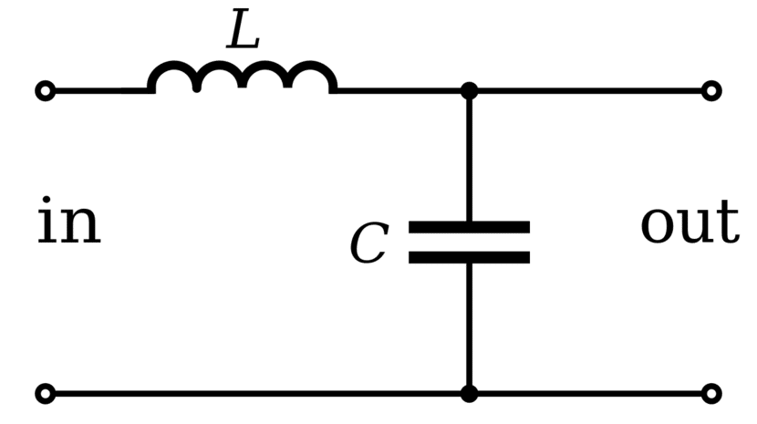
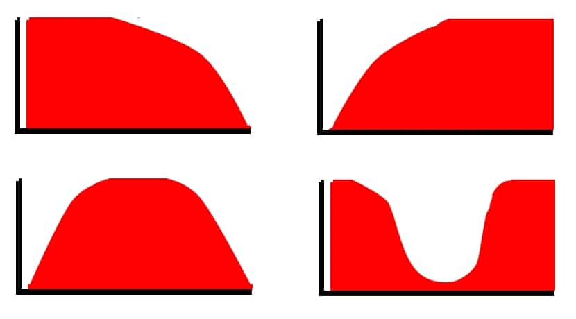
- Low pass filter: they are so called because they are those filters that let the lowest frequencies pass and suppress or reduce the pass of the higher frequencies. They consist of one or more coils (in series with the power supply and load), and one or two shunt capacitors with the power supply and load. Remember that the load is understood to be the device connected to the filter and that collects the filter's output ... Within these filters there are also variants, such as L, T and π.
- High pass filter: the high pass filter is the opposite of the low pass, in this case, what it will filter or limit is the low frequency pass, letting the higher frequencies pass. In this the electronic elements that compose it are invested. That is, here the capacitors will be the ones in series with the power supply and the load, while the coils will be shunted. There are also the same subtypes as in the case of low pass filters.
- Band pass filter: This type of filter exerts two frequency band pass rate blocks. That is, they act both as a low pass filter and as a high pass filter, opposing the passage of the lowest frequencies and also the highest at the same time. In other words, it only allows the middle frequencies to pass through.
- Band filter: it is exactly the opposite of the previous one, what it does is that it filters the pass of the mid frequencies and only allows the lowest and highest frequencies to pass through.
Remember that the inductances they let through low frequencies and oppose the passage of high frequencies. Instead, capacitors they let through high frequencies and oppose the passage of low frequencies.
I would like to add that filters on a practical level they are not perfect, and they can always pass some low or high frequencies that you should block. However, they do their job quite well for most applications.
And finally, I would also like to clarify another thing, and that is that you have surely heard about the EMA and DEMA filters. EMA (Exponential Moving Average) filters allow to implement this type of filters in a simple way in embedded devices. As for DEMA (Double Exponential Moving Average), they have a faster response than EMA, maintaining a good suppression of the noise that you want to avoid.
Alpha factor
El alpha factor, which you will see that appears in the Arduino IDE codes in the next section, is the parameter that conditions the behavior of the exponential filter. It is related to the cutoff frequency:
- Alpha = 1: that provides a signal to the unfiltered output.
- Alpha = 0: the filter value will always be 0.
- Alpha = x: other values can get other alterations in the EMA filter. If you decrease the Alpha factor, you will soften the frequency signal obtained more, and the response time of the system is also increased (it takes longer to stabilize).
Filters and Arduino
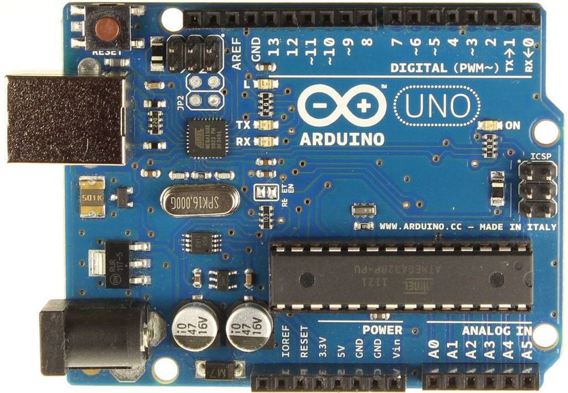
You should know that it is not necessary to create the circuit high pass filter or low pass filter to connect it to your Arduino board and work with it. Although you can experiment and create these kinds of simple filters, you can also test how an EMA would work with just the Arduino board and a simple code for the Arduino IDE. It is the only thing you need to see how it is in charge of filtering some frequencies (in this case the action is simulated and some integers / floats are simply filtered simulating what I would do filter actually).
Here are some code samples that you can use to practice.
Example of simple digital filter in Arduino of type low pass:
float   lowpass_prev_out[LOWPASS_ANALOG_PIN_AMT],
         lowpass_cur_out[LOWPASS_ANALOG_PIN_AMT];
int        lowpass_input[LOWPASS_ANALOG_PIN_AMT];


int adcsample_and_lowpass(int pin, int sample_rate, int samples, float alpha, char use_previous) {
  // pin:            Pin analógico de Arduino usado
  // sample_rate:    El ratio adecuado
  // samples:        Samples
  // alpha:          El factor Alpha para el filtro paso bajo
  // use_previous:   Si es true se sigue ajustando hasta el valor más reciente.

  float one_minus_alpha = 1.0-alpha;
  int micro_delay=max(100, (1000000/sample_rate) - 160);
  if (!use_previous) {
    lowpass_input[pin] = analogRead(pin);
    lowpass_prev_out[pin]=lowpass_input[pin];
  }
  int i;
  for (i=samples;i>0;i--) {
    delayMicroseconds(micro_delay);
    lowpass_input[pin] = analogRead(pin);
    lowpass_cur_out[pin] = alpha*lowpass_input[pin] + one_minus_alpha*lowpass_prev_out[pin];
    lowpass_prev_out[pin]=lowpass_cur_out[pin];
  }
  return lowpass_cur_out[pin];
}

int resulting_value;

void setup() {
   Serial.begin(9600);
   resulting_value = adcsample_and_lowpass(0, 1000, 300, 0.015, false);
}

void loop() {
   resulting_value = adcsample_and_lowpass(0, 1000, 150, 0.015, true);
   Serial.println(resulting_value);
Code example for Arduino type High pass:
int sensorPin = 0;    //pin usado para el ADC
int sensorValue = 0;  //Inicia sensor variable equivalente a EMA Y
float EMA_a = 0.3;    //Inicialización del EMA Alpha
int EMA_S = 0;        //Iniciación del EMA s
int highpass = 0;

void setup(){
  Serial.begin(115200);
  EMA_S = analogRead(sensorPin);
}

void loop(){
  sensorValue = analogRead(sensorPin);              //Lee el valor del sensor ADC
  EMA_S = (EMA_a*sensorValue) + ((1-EMA_a)*EMA_S);  //Ejecuta el filtro EMA
  highpass = sensorValue - EMA_S;                   //Calcula la seña alta

  Serial.println(highpass);

  delay(20);                                //Espera 20ms
}
Arduino code example band pass:
int sensorPin = 0;        //Pin para el ADC
int sensorValue = 0;      //Inicia la variable del sensor, equivale a EMA Y

float EMA_a_low = 0.3;    //Inicia EMA Alpha
float EMA_a_high = 0.5;

int EMA_S_low = 0;        //Inicia EMA S
int EMA_S_high = 0;

int highpass = 0;
int bandpass = 0;

void setup(){
  Serial.begin(115200);

  EMA_S_low = analogRead(sensorPin);
  EMA_S_high = analogRead(sensorPin);
}

void loop(){
  sensorValue = analogRead(sensorPin);    //Lee el valor del sensor ADC

  EMA_S_low = (EMA_a_low*sensorValue) + ((1-EMA_a_low)*EMA_S_low);  //Ejecuta EMA
  EMA_S_high = (EMA_a_high*sensorValue) + ((1-EMA_a_high)*EMA_S_high);

  highpass = sensorValue - EMA_S_low;
  bandpass = EMA_S_high - EMA_S_low;

  Serial.print(highpass);
  Serial.print(" ");
  Serial.println(bandpass);

  delay(20);
}
Arduino code example for band:
int sensorPin = 0;          //Pin usado para el ADC
int sensorValue = 0;        //Inicio para EMA Y

float EMA_a_low = 0.05;     //Inicio de EMA alpha
float EMA_a_high = 0.4;

int EMA_S_low = 0;          //Inicia EMA S
int EMA_S_high = 0;

int highpass = 0;
int bandpass = 0;
int bandstop = 0;

void setup(){
  Serial.begin(115200);

  EMA_S_low = analogRead(sensorPin);
  EMA_S_high = analogRead(sensorPin);
}

void loop(){
  sensorValue = analogRead(sensorPin);      //Lee el valor del sensor ADC

  EMA_S_low = (EMA_a_low*sensorValue) + ((1-EMA_a_low)*EMA_S_low);          //Ejecuta EMA
  EMA_S_high = (EMA_a_high*sensorValue) + ((1-EMA_a_high)*EMA_S_high);

  bandpass = EMA_S_high - EMA_S_low;

  bandstop = sensorValue - bandpass;

  Serial.print(sensorValue);
  Serial.print(" ");
  Serial.print(EMA_S_low);
  Serial.print(" ");
  Serial.println(bandstop);

  delay(20);
}
I advise you to modify and experiment with these codes. The result you can see very graphically thanks to the Serial Plotter of the Arduino IDE ... Remember that if you have questions about Arduino programming or how to use the IDE, you can download the free HwLibre course in PDF.