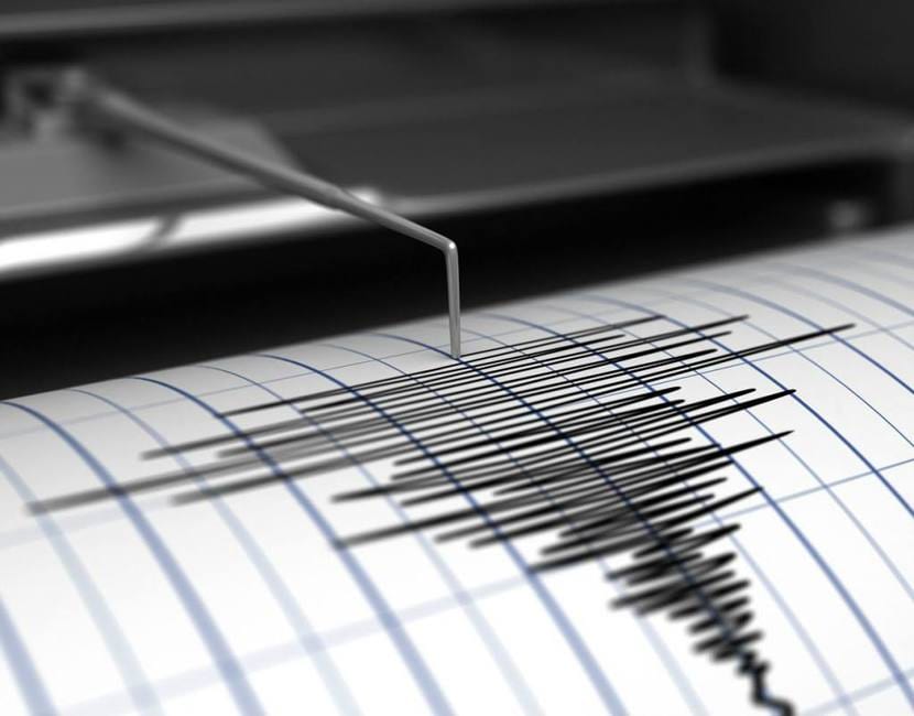
Un seismograph or seismometer is a device that allows to measure movements of the earth's surface, that is, earthquakes or tremors of any kind. In general, they are used to measure those produced by the movement of tectonic or lithospheric plates, and thus be able to carry out studies and predict possible earthquakes. The invention was created by Scotsman James David Forbes in 1842.
The instrument of that time was primitive, and consisted of a pendulum that, due to its mass, remained immobile due to inertia. While all the other parts of the machine moved around him. The pendulum had an awl at its end and allowed writing on a roller of time-bound paper. In this way, when the ground vibrated, it was represented on said paper in the form of curves.
Little by little the measuring instruments evolved to adapt to new scales to measure only tremors that people could feel. Since then, the development has been constant until the new ones with much more precision and much more sensitive for the different tasks of geologists and other personnel who usually use this type of measure. With the arrival of electronics, these devices have been modernized and become much more sophisticated until they reach the current seismographs.
Currently, seismographs can receive information from tremors from different points on Earth. Those near the epicenters can take earthquake readings to record calls S waves and P waves. On the other hand, the most distant ones can only record P waves. And in case you didn't know, the sensors placed on the ground to capture these earthly vibrations are called geophones, although in the sea a complementary hydrophone is also used to measure the acoustic waves that they are transmitted by water when an earthquake occurs.
How to mount the seismograph
If you are passionate about this type of device, and a maker, you can do your own DIY seismograph for just under € 100...
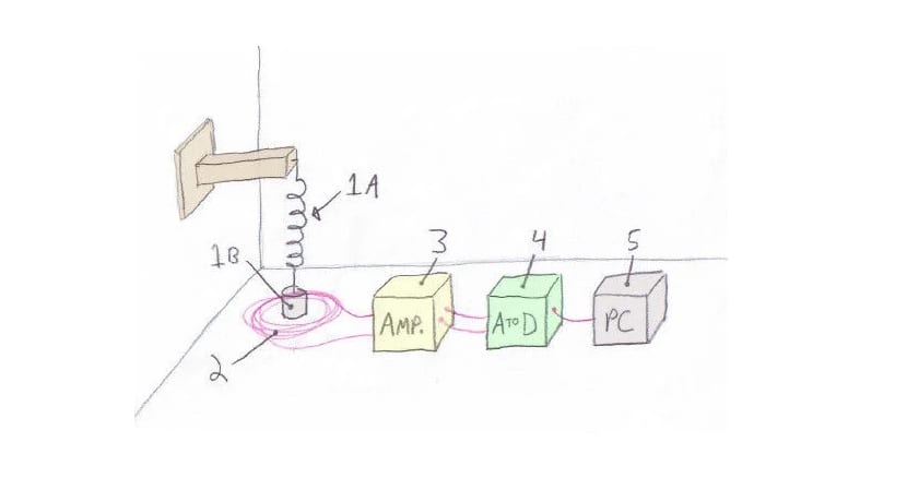
El operation of this project It is quite simple, as can be seen in the diagram in the image above. The homemade seismograph will detect the movement of the ground thanks to a magnet that hangs from a spring so that it can bounce up and down freely.
A stationary coil of wire is placed around the magnet on the reference surface. Thanks to it, any movement no matter how small the magnet makes will be detected, since will generate currents in the cable that can be measured with precision. The rest of the device is the electronics necessary to transform that electronics into data that can be recorded and viewed on the screen of our PC.
Necessary materials
In order to create such a system, you will need a few quite basic elements and that we all have at our fingertips. The full list is:
- Un metal spring. It may be the typical one of the famous Slinky, Jr. toy, those you see in some movies that pull down some stairs and go down alone ...
- Ring magnet make it powerful (RC44), for example made of neodymium.
- Amplifier OpAmp LT1677CN8 signal signal, and coil of copper wire Magnetic (42 gauge varnish insulated) to convert weak signal to stronger signal. (MW42-4)
- PVC Pipes to wind the cable.
- A device capable of converting the analog signal into digital. In this case it is used Arduino.
- A recording and recording device. In this case, software running on our pc to represent what Arduino picks up ...
- Modular made of wood, metal or plastic to hold the spring.
- Breadboard or plate printed circuit board for soldering.
- ECT and Müllen. 10K and 866K
- capacitors 0.01uF, 0.1uF, 1uF, 330pF
- Cables for connection
Step by step procedure
Step 1:
First you must wind some copper wire with insulation to create a coil. In this project they use PVC pipes that you can find in any plumbing. The tubing is cut and you will leave about 1 inch (2.54 cm) where it is wrapped with 2500 turns of thread. Remember that it must be insulated with some varnish, they are already sold like that in some establishments.
You can also create a piece with a 3D printer if you prefer, or use other types of recycled materials to replace the PVC pipe ... Another option is to use the spools themselves where the wound thread comes if you have a pair of them. And to wrap the wire, you can use the help of a sewing machine or a drill as seen in the video.
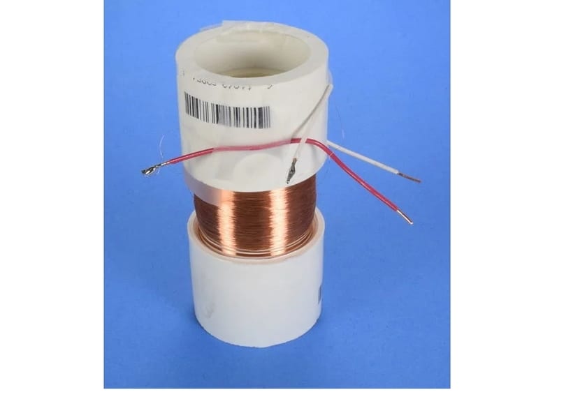
Remember you must solder normal wires to both ends of the coil's copper wire. With them you will be able to make the connections better, since the copper wire of the coil is extremely thin to be able to work with it and then connect it to the Arduino board.
Step 2:
The next step is hang and calibrate the spring with the magnet. For this you must put the magnets glued to the wire or spring. They should be suspended inside the pipe with the winding you created in the previous step. You must calibrate well the distance at which you hang it on the wooden, metal or whatever you use support ..., so that when there is a tremor, the spring moves the magnet right in the center of the coil so that it can induce a current in it .
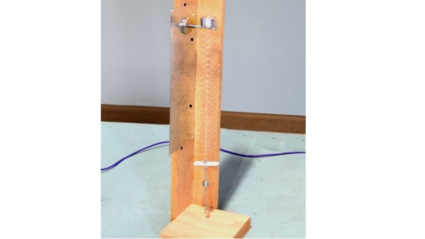
In addition, the calibration should make the vibration is 1Hz, that is, it moves up and down once per second. Up and down is the complete cycle that must be done in one second.
Step 3:


For amplify the induced current in the coilSince moving the magnet in the coil core generates very small currents, a signal amplifier is needed. There are several types of good signal boosters, you can use any one. The connection is simple, you can do it on a breadboard or on a perforated plate by flooring, if you are going to leave it permanent. You simply have to connect the circuits as shown in the image ...
Step 4:
Now let's the arduino board UN, which will be in charge of transforming the signal amplified by the circuit from the previous step and transforming it into digital data. The seismograph is based on another TC1 project where you can find more details about the Arduino configuration.
Step 5:
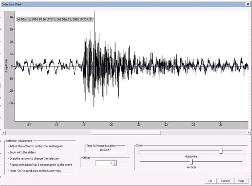
When you connect Arduino to the PC, through the USB, the data will be captured, and by means of a software the data will be able to be loaded through the serial port monitor that you have in Arduino IDE. Everything should show the proper data, if not, check that it is properly connected to the correct COM port.
You can use jAma SixIt is an interesting project and being able to see and share data with other students and scientists around the world.
You could also make some tweaks and improvements to reduce noise and prevent you from giving some false information. The system is quite sensitive, so it can record tremors that are not really earthquakes. It may also pick up vibrations from some nearby appliances or vehicles. Now do Purge and Error! Until I tune it ...
Source:
Instructables - diy seismometer