To use with Arduino there are multitude of electronic components you can use. These devices are not only exclusive to Arduino, but they are the most practical for your projects. An example of this are transistors MOSFETs that we have described in previous articles. But this time we will tell you everything you need to know about a specific one: IRFZ44N.
Sometimes you will find yourself working with a project in which you need to activate a load with a microcontroller. For that to be possible with the voltages handled by the current MCU chip It is necessary to solve certain problems to be able to act on transistors MOSFETs with voltages that can go from 5v to 3.3v or less.
IRFZ44N

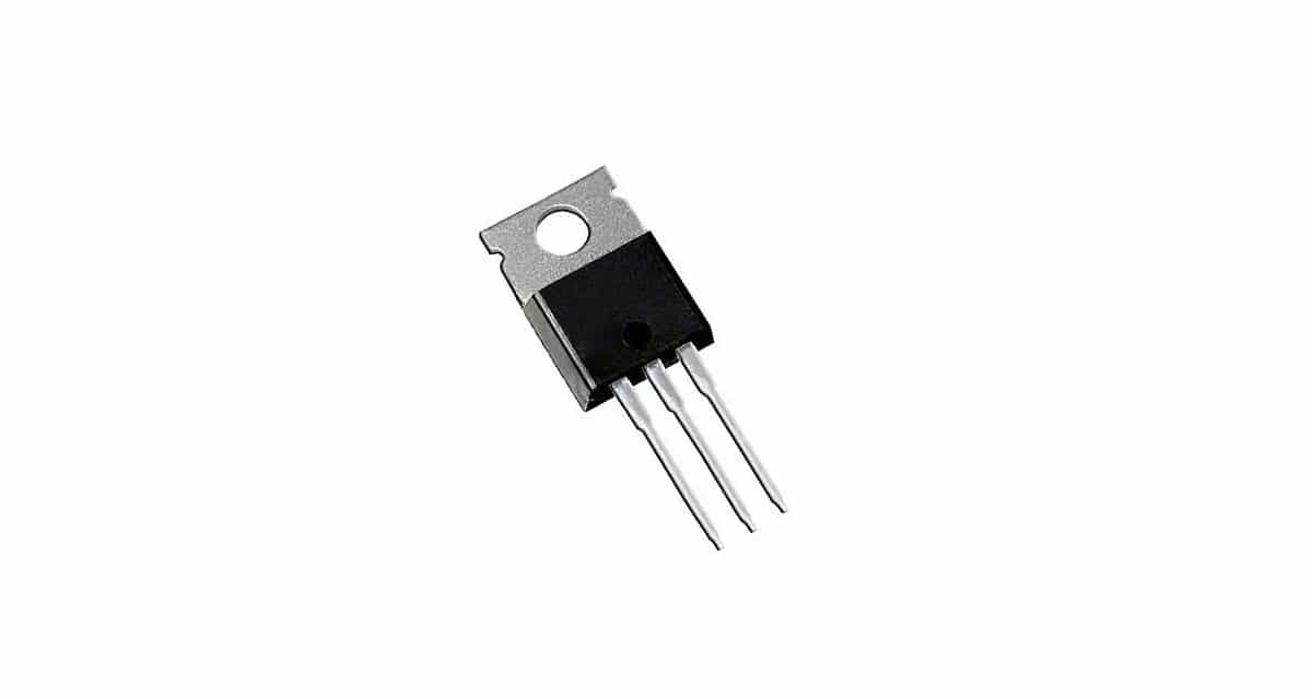
Well, the IRFZ44N is a MOSFET transistor as I have already commented. It has a TO-220-3 type packaging, although it can be presented in other formats, and with a fairly simple pinout with the three typical pins for the door, drain, source (in that order from left to right if you look at it from the back) , that is, where it has the inscriptions). It can be manufactured by very different manufacturers, so you can consult the concrete datasheet.
This MOSFET has a N-type channel, As its name indicates. In addition to that, it has other technical details such as:
- Drain-source separation voltage: 60v
- Continuous drain intensity: 50A
- rds: 22mOhms
- Gate-source voltage: 20v
- Operating temperature range: -55 to 175ºC
- Power dissipation: 131w
- Fall time: 13ns
- Establishment time: 55ns
- Shutdown delay: 37ns
- Typical connection delay: 12ns
- Price: a few cents. You can buy a 10 pack IRFZ44N on Amazon for less than € 3.
Application example with Arduino
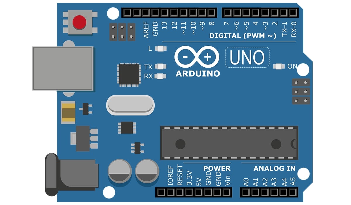
Let's put an application example for the IRFZ44N with Arduino and its pins PWM. And it is that when you need to control loads in a variable way to regulate the speed of motors, the intensity of lighting, etc., you can go to these PWM pins and transistors like the one we have to analyze today.
First of all, when you want to connect or disconnect a housing from a power source, it is usually use a classic switch or a relay. But that only allows turning on and off, both in one case and in the other.
With a transistor it can be controlled with an electrical signal, as with the relay, to automate the control, and you will also have a series of advantages such as variable control of the load to be able to do it by means of PWM. Instead, it also involves some complications such as calculations of currents to be switched, working voltages, etc.
By exampleImagine that you need to run a 12v electric motor at half its rated speed. You will already know that in practice it would not be worth lowering the power to 6v without more ... it is most likely that they would remain immobile increasing their temperature and with the risk of damaging the element.
Instead, what is done with PWM is to apply several impulses to the nominal voltage in a period of time connecting and disconnecting (pulses) so that the motor works as you want, as we saw in the PWM article, and modeling the working speed of the motor without affecting the torque or motor torque .
So far everything is correct, but ... what would happen in a lighting application? Well, unlike the motor, where there is inertia, in the lighting, if it is switched as with PWM at a low frequency, annoying flickers occur that we would hardly appreciate in the motor. However, even in the case of the engine, some long-term mechanical problems could be created by going "jerk".
And what does all this have to do with the IRFZ55N? Well, if you want smooth operation with PWM, this device could solve all those problems. In addition, it could control up to currents of 50A, which offers extraordinary capacity for some more powerful motors. Remember that as I said before, the problem with the Arduino PWM pins is that their voltage is not enough to control certain elements, such as a 12v, 24v motor, etc., so the transistor and an external source can help you .
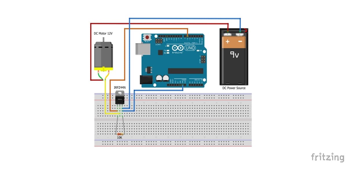
With Arduino and a motor, with this simple connection diagram that you can see, you can get a practical example of what I have commented. So you can control 12v motor with the IRFZ44N MOSFET in a simple way.
For you to better understand the operation of the IRFZ44N transistor for this type of application, the serial monitor will be used from where you will be able to enter understood values y entre 0 255 to be able to modulate the motor and observe the results.
As to sketch code for Arduino IDE, it would also be simple
int PWM_PIN = 6;
int pwmval = 0;

void setup() {
  Serial.begin(9600);
  pinMode(PWM_PIN,OUTPUT);
  Serial.println("Introduce un valor entre 0 y 255:");
}

void loop() {
  if (Serial.available() > 1) {
      pwmval =  Serial.parseInt();
      Serial.print("Envío de velocidad a: ");
      Serial.println(pwmval);
      analogWrite(PWM_PIN, pwmval);
      Serial.println("¡Hecho!");
  }
Remember that for more information about Arduino programming, you can download our free course in PDF.
Excellent page and description of the irfz44n workhorse…. I have already done experiments with it and it is versatile and strong with its 5th amps, greetings
Parabéns pala matéria, and unimaginável or great value that these information have for me, I am very pleased, now you can conclude my project with much less custody and with much more power!
Hello, I have a question, if I put a voltage of 12v in the gate with a pulldown and the source to ground, that ground helps me to put a zero in a microcontroller (3,3v).
the idea is to sense a point of a certain circuit and know if it is energized with 12v or not and report it to a microcontroller