All the logic gates are the basis of digital electronics. For this reason, they are very important, and if you want to start working with them, you should know what they are, how they are constituted, and their function. So you can use the series of chips that exist in the market that have this type of doors so that you can start making your own projects working with this logic.
These doors, combined with other Electronic components, and even with plates like Arduino, they can give a lot of play to makers as you can see for yourself.
What are logic gates?
All the logic gates they are fundamental elements of digital logic for the implementation of digital electronic circuits. These gates provide low (0) or high (1) voltage signals at their output depending on the state of their inputs. They generally have one exit and two entrances, but there may be doors with more than 2 entrances. In addition, there are peculiarities such as the inverting gate or NOT, it has only one input and one output.
Thanks to these Boolean inputs and outputs you can get elementary binary logic operations, such as addition, multiplication, negation, etc.
How are they implemented?
-

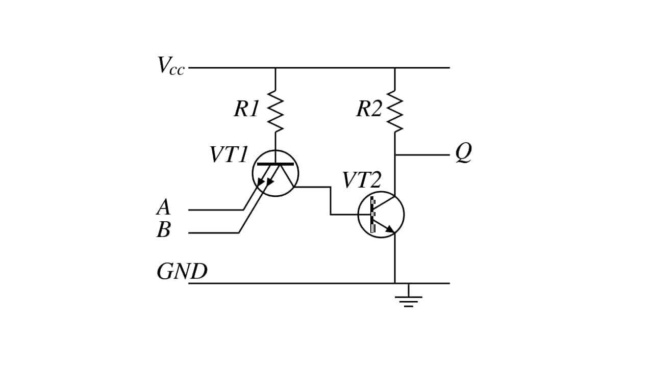
- NAND gate in TTL
-
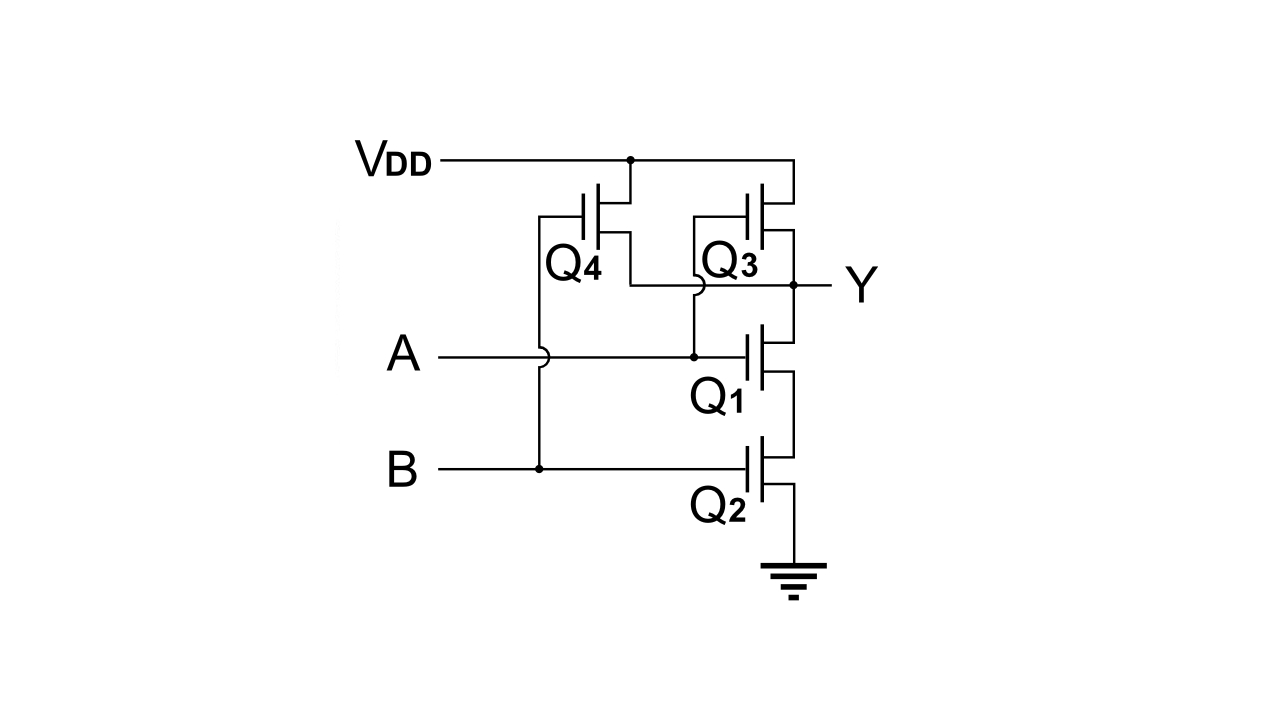
- NAND gate in CMOS
Logic gates can not only be implemented in one way. In fact, that's why there are different logical families. Each of these families will implement the gate in one way, using different electronic components.
By exampleIf TTL is used for the chip, the gates will be made up of bipolar transistors, while the CMOS logic is based solely on MOSFET transistors. In addition to these two families, which are usually the most popular, there are also others such as BiCMOS (combines bipolar and CMOS transistors), RTL (resistors and bipolar transistors), DTL (diodes and transistors), ECL, IIL, etc.
There is not one family much better than another, it will depend on the application. But nevertheless, CMOS It is one of the most used in advanced circuits, such as CPU, MCU, GPU, memory, etc. For other simpler circuits it is also common to find the TTL.
Applications
The applications of these logic gates are endless. With these essential "bricks" you can build multitude of digital circuits. From a simple adder, to a complex CPU, through many other circuits that you can imagine. In fact, many of the systems that you use every day, such as your PC, your TV, mobile, etc., have billions of logic gates.
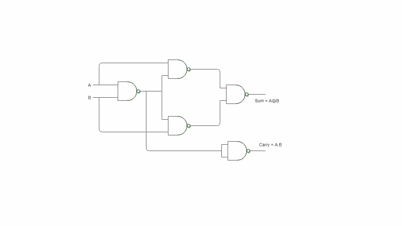
Un practical example of application of logic gates would be this simple adder that you can see in the image above. It is a very simple circuit, which is capable of adding two bits (A and B) in its inputs to give the Sum result, and also the Carry, that is, what you take away ... You can see the results it would give in the following table:
| A | B | Sum | Carry | Binary result |
|---|---|---|---|---|
| 0 | 0 | 0 | 0 | 00 |
| 0 | 1 | 1 | 0 | 01 |
| 1 | 0 | 1 | 0 | 01 |
| 1 | 1 | 0 | 1 | 10 |
If you look at this table, if you add 0 + 0 in binary it gives you 0, if you add 1 + 0 it is 1, but if you add 1 + 1 it would give 2, which in binary system corresponds to 10.
Types of logic gates
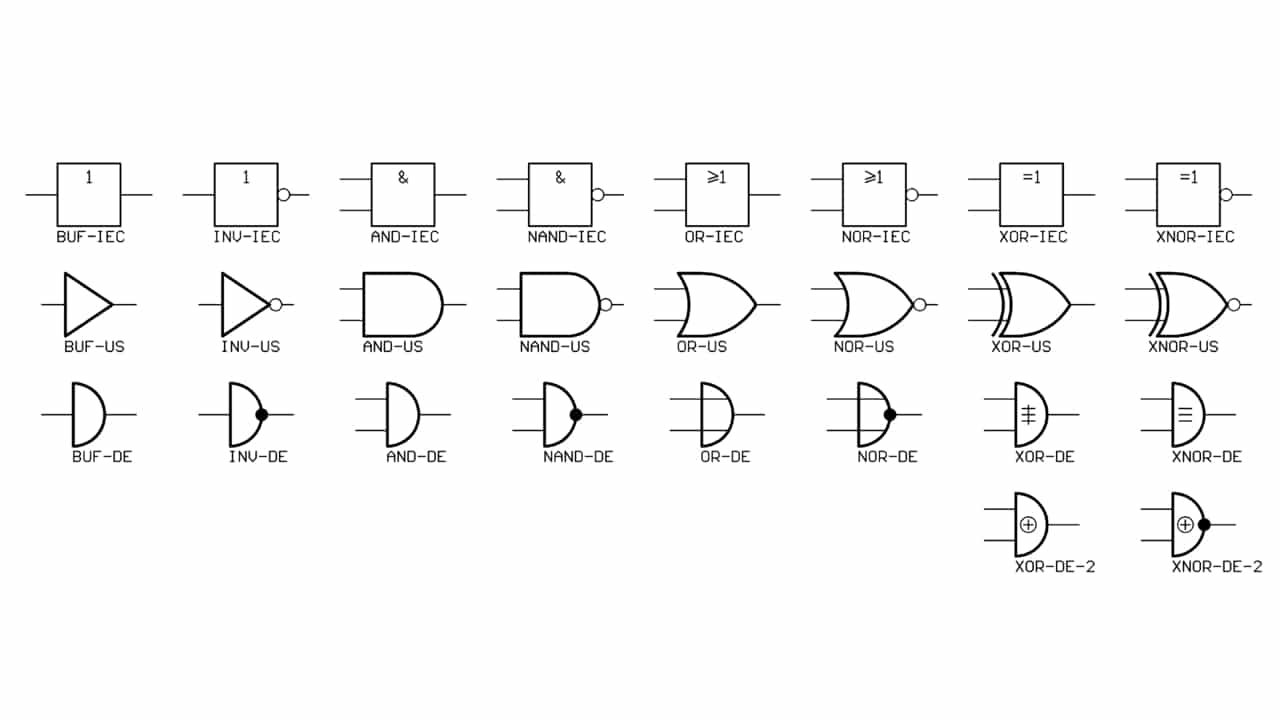
As for types of logic gates, you have a good number of them, although the most used are the following (with their truth tables):
- Buffer (Yes): it is known as buffer or direct gate, since its output will have the same state as its input. Although it may seem useless, in many logic circuits it is often used as a current amplifier or as a voltage follower.
| Home | Departure from |
|---|---|
| 0 | 0 |
| 1 | 1 |
- NOT (inverter): is the logical negation (¬ o '), that is, it inverts the bit at its output.
| Home | Departure from |
|---|---|
| 0 | 1 |
| 1 | 0 |
- AND: this other gate performs a product function (·) of the binary bits of its input. That is, it would be like multiplying A and B. Therefore, anything by zero is zero, it would only give one to its output if both inputs are 1. Hence its name 1 AND 1.
| A | B | S |
|---|---|---|
| 0 | 0 | 0 |
| 0 | 1 | 0 |
| 1 | 0 | 0 |
| 1 | 1 | 1 |
- GOLD): this other gate performs a logical addition operation (+). That is, Either one of its outputs OR the other, OR both must be at 1 for its output to be 1. When both are 0, the output is 0 as well.
| A | B | S |
|---|---|---|
| 0 | 0 | 0 |
| 0 | 1 | 1 |
| 1 | 0 | 1 |
| 1 | 1 | 1 |
- XOR (or exclusive): This exclusive OR performs the Boolean function A'B + AB ', and its symbol is
. In this case, if its two inputs are equal, the output is 0. If they are different, then it will be 1.

| A | B | S |
|---|---|---|
| 0 | 0 | 0 |
| 0 | 1 | 1 |
| 1 | 0 | 1 |
| 1 | 1 | 0 |
- NAND (Y negated): is the negated logical product, that is, the inverse of the AND. It's like using a NOT on the AND output to invert the output bits. Therefore, the results are:
| A | B | S |
|---|---|---|
| 0 | 0 | 1 |
| 0 | 1 | 1 |
| 1 | 0 | 1 |
| 1 | 1 | 0 |
- NOR (Or denied): the negated logical sum, or what is the same, an OR with its negated output, resulting in the inverse of the OR.
| A | B | S |
|---|---|---|
| 0 | 0 | 1 |
| 0 | 1 | 0 |
| 1 | 0 | 0 |
| 1 | 1 | 0 |
- XNOR (exclusive NOR): it's like applying the binary complement to an XOR gate. That is, perform the AB + A'B 'operation. A times B added to A times B denied. Therefore, the outputs will be like those of the inverted XOR:
| A | B | S |
|---|---|---|
| 0 | 0 | 1 |
| 0 | 1 | 0 |
| 1 | 0 | 0 |
| 1 | 1 | 1 |
Both NOR and NAND are two of the most interesting gates, since they are known as universal logic gates. That is, you can make circuits only with them to represent any other type of logic gate. This is important, since if you buy chips with these doors, you can have all the functions. For example, if the two inputs of a NOR are bridged or a NAND is equivalent to a NOT. You have more equivalents here:
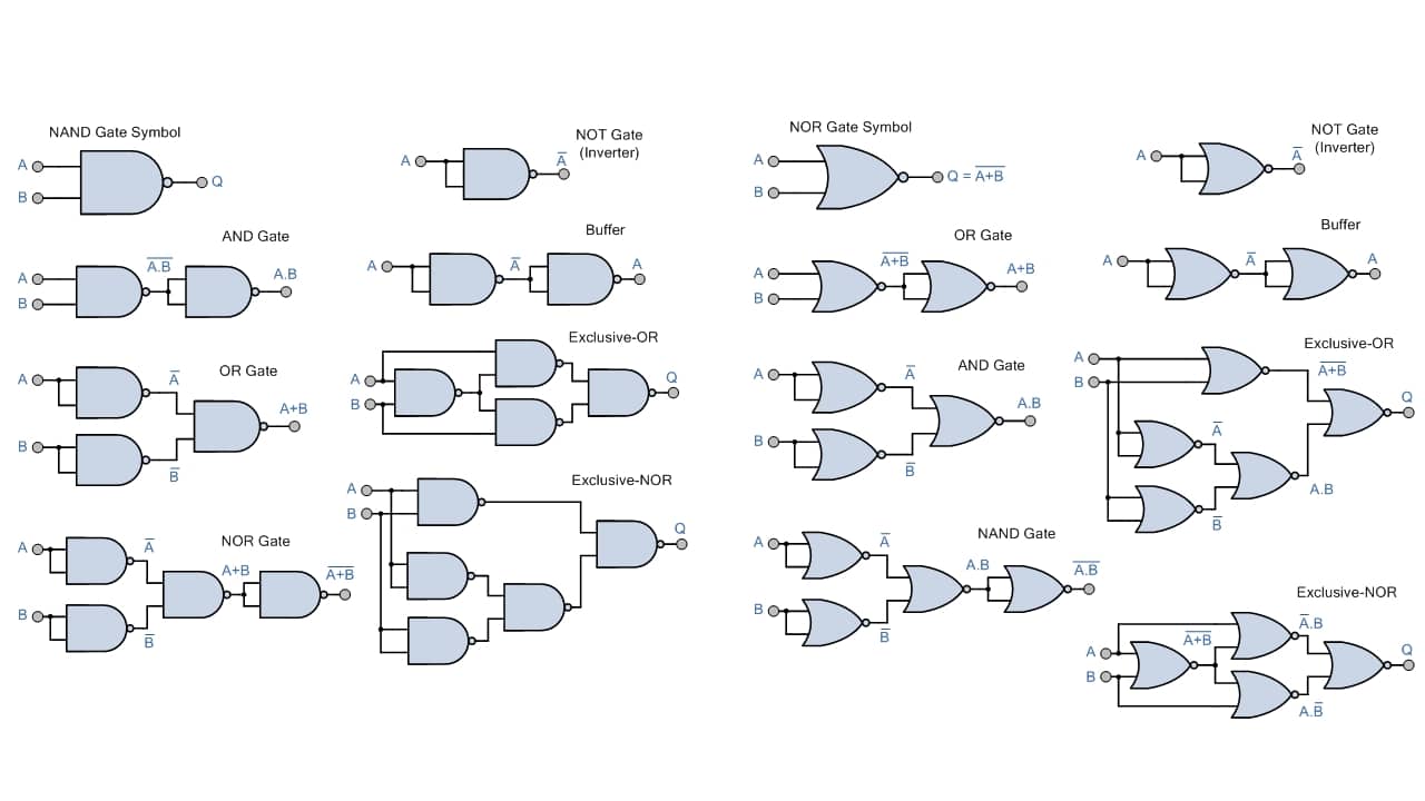
Functions: electronics-tutorials.ws
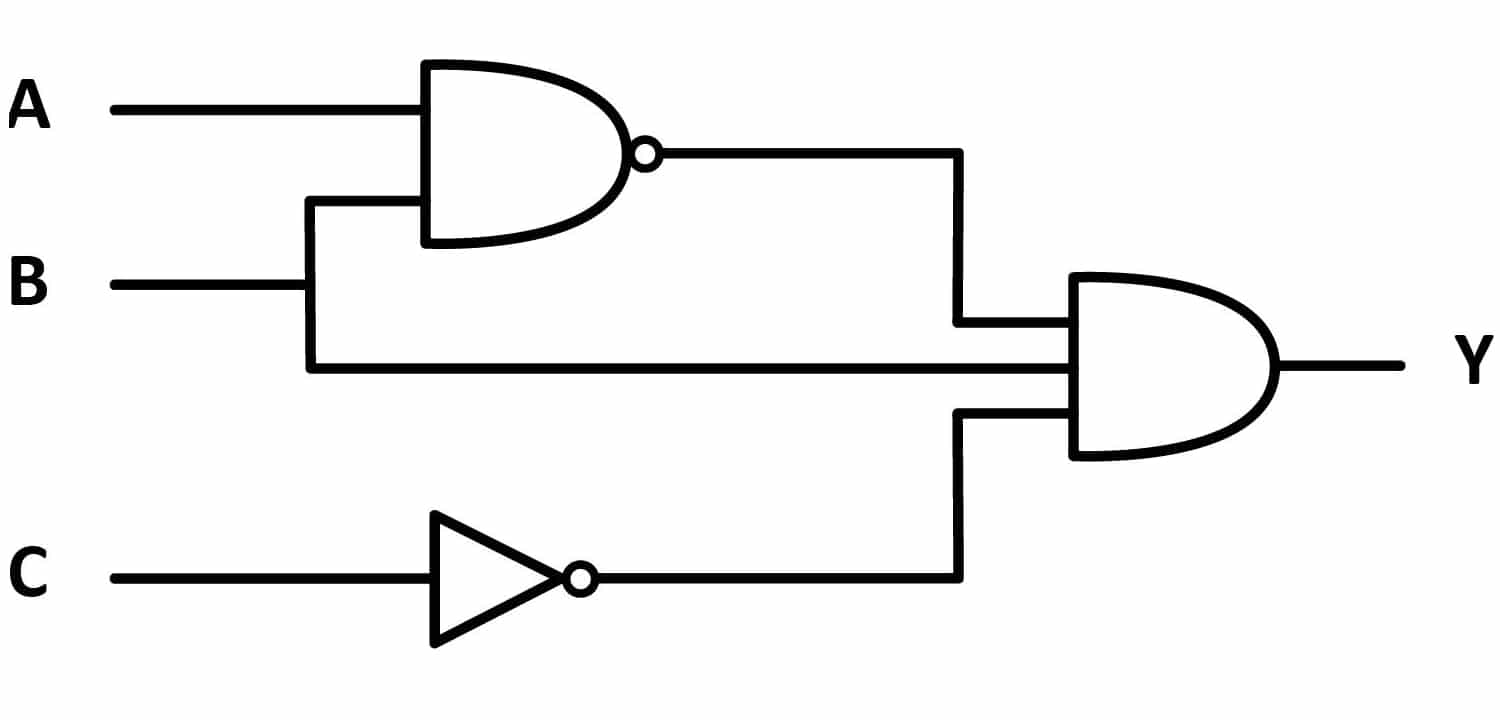
Te I adviseTo learn more, Google a simple circuit with any gates. And to find out what it does, do a kind of "reverse engineering", follow the lines of the inputs and outputs and see the status of each line according to the inputs given to the output.
By exampleIf you look at the image above, the equivalence diagram of an OR with NAND gates, you will see that it consists of two NAND gates with their output bridged and both outputs go to another NAND. Keep the following in mind:
- If you go to the NAND truth table, you will see that when its two inputs are 0 the output is 1, and when its two inputs are 1 the output is 0.
- As they are bridged, if the input is 1 (one enters both), the result is 0. And when the input is 0 (both zero), the output will be 1, which is equivalent to a NOT.
- Therefore, we have two NOTs for bits A and B. At their output we will therefore have A 'and B'.
- Those two negations go into the last NAND, which will perform an inverse logical product of those two bits.
- According to the laws of logic, this equates to the direct sum, that is, A + B. Therefore, the final result will be as if it were an OR ...
Logic Gate Chip Series - Where to Buy
-

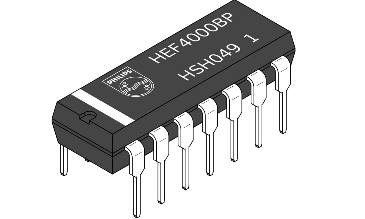
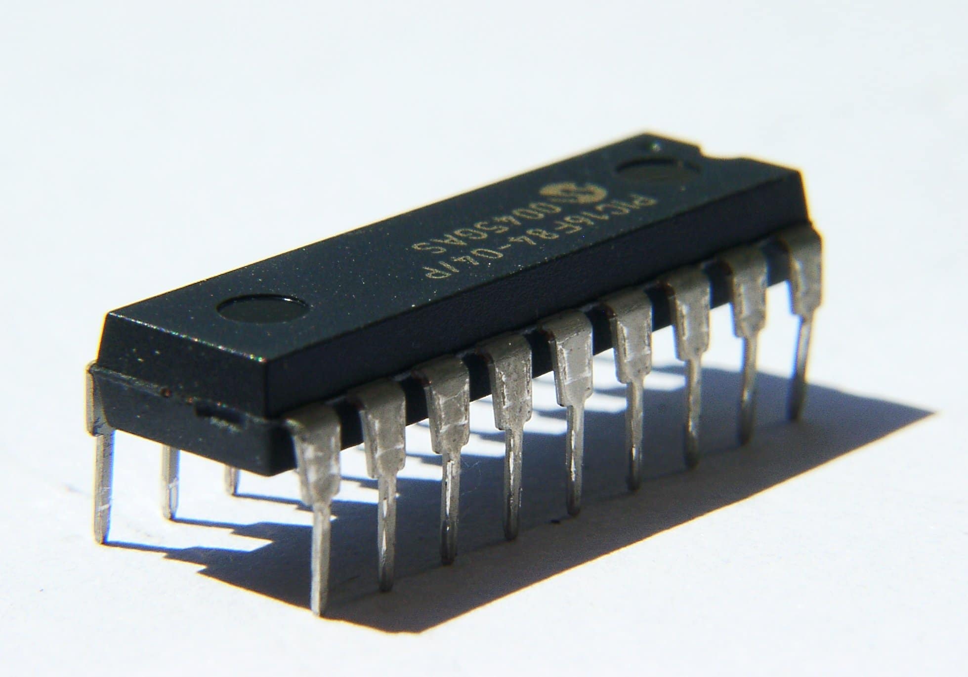
- Logic gate DIP chip
-
- Internal diagram of the chip
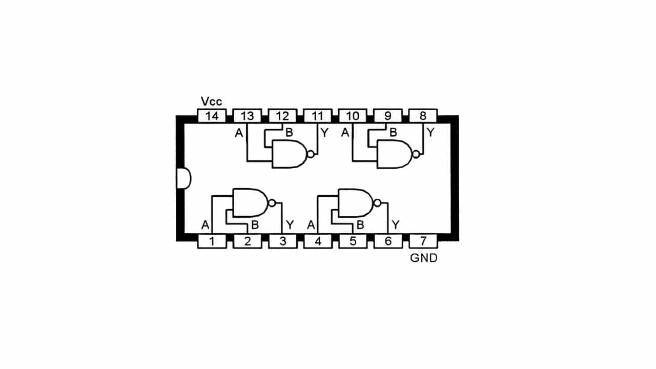
In stores specialized in electronics you can buy cheap chips with logic gates to start using in your projects. These chips are not a single logic gate, but they allow you to have several of them so that you can link their inputs and outputs as you need. For example, in the diagram in the image above you can see a typical pinout of a DIP chip with 4 NAND gates. In addition, it also has two pins for power (Vcc and GND).
Here are some purchase recommendations:
- No products found..
- Huaban: 30-chip kit with universal NAND gates.
- Zebulon: 120 CMOS chip kit.
Other resources
In order to learn more about how to implement these gates and how to start creating circuits with them, you can make use of these Another resources what do I recommend:
- SimulIDE software to be able to simulate the operation of these circuits with gates. It's free, open source, and cross-platform.
- Online binary calculator (You can also use your operating system's calculator in binary mode).
- No products found..
- Digital Logic Circuits Book: from design to experiment.
Digital logic with Arduino
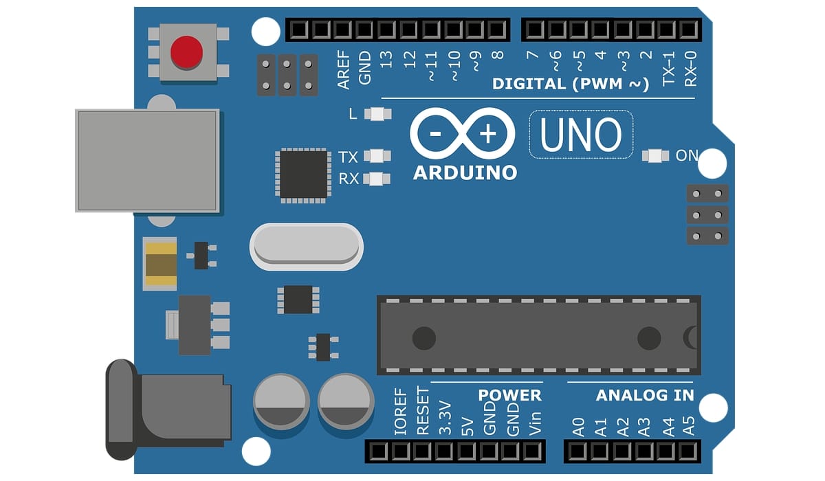
Other resource what do you have in your hands if you already have a plate Arduino UNO in your hands is use Arduino IDE to create sketches that simulate these logic functions to, for example, see the result in a more visual way with an LED that simulates the output of the door. For example, putting an LED on pin 7 and using 8 and 9 as inputs A and B:
int pinOut = 7;
int pinA = 8;
int pinB = 9;

void setup()
{
pinMode(pinOut, OUTPUT);
pinMode(pinA, INPUT);
pinMode(pinB, INPUT);
}
void loop()
{
boolean pinAState = digitalRead(pinA);
boolean pinBState = digitalRead(pinB);
boolean pinOutState;
//AND
pinOutState =pinAState & pinBState;
digitalWrite(pinOut, pinOutState);
}
An AND (&) function has been used here, as you can see, but you can replace that line of code under the // AND line with others to use other logic functions:
//OR
pinOutState = pinAState | pinBState;

//NOT
pinOutState = !pinAState;

//XOR
pinOutState = pinAState ^ pinBState;

//NAND
pinOutState = !(pinAState & pinBState);

//NOR
pinOutState = !(pinAState | pinBState);

//XNOR
pinOutState = !(pinAState ^ pinBState);