
If you are a music lover or directly an amateur or professional musician, surely in your home you have accumulated a large collection of musical instruments. To make all these mix perfectly, it is best to get a MIDI controller. Unfortunately, these types of objects are usually quite expensive, so it is difficult for a person without too many resources to access everything they can offer.
To understand much better what a MIDI controller is, tell you that the word MIDI comes from Musical Instrument Digital Interface, that is, a kind of controller that makes electronic musical devices can communicate with each other. If you have an electronic keyboard at home, for example, it is more than likely that it has a MIDI interface. Before continuing to advance, despite the fact that there are certain technical details that may lead one to believe otherwise, it must be very clear that MIDI is not audio.
Create your own MIDI controller with this simple tutorial
Once we are clear about this, it will surely be much easier for you to understand that MIDI is just a simple instruction set capable of supporting up to 16 independent channels, which means that there can be up to 16 different devices communicating independently with each other. These devices have to be connected through a 5-pin DIN cable, which is basically a cable with five pins inside a connector. As a detail, it is quite common to use a USB instead of a 5-pin DIN, in case of using a USB we must create a USB-MIDI interface.
Without further ado, I leave you with the link where you can find the tutorial step by step with a lot of descriptive images where we can perform all the necessary actions to create our own MIDI controller.
How to make your own MIDI controller with Arduino

Many are the people who need, for different reasons both personal and professional, to use a fully custom MIDI controller Because perhaps and as an example, at some point in your life as an artist, buying an inexpensive MIDI controller may not meet your expectations or needs while, when the time comes, opting for a professional version may be excessive in both financial resources you need, as well as the large number of features they can offer.
Due to this, today I want to show you everything you need so that you can make your own MIDI controller, indicating both everything you need for its construction and offering you the software that you will need to install. As a detail, for this project the use of an Arduino board is essential, a controller that is powerful enough to carry out this task.

What is a MIDI controller?
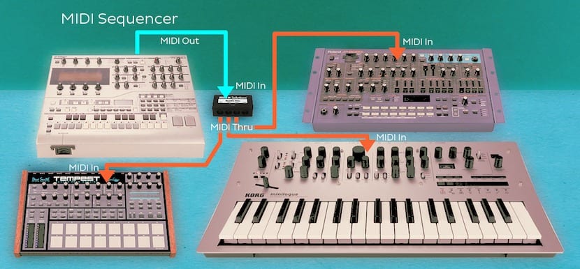
Basically, a MIDI controller is responsible, broadly speaking, for connecting different musical devices to each other. Many are the instruments that incorporate a MIDI interface, although this must be very clear since there are many users who are often confused, MIDI is not an audio file, but a very simple set of instructions that an instrument can receive. to make different control or sound settings.
Inside MIDI there are two different typesOn the one hand we have the one called Change Control where it has the controller number and a value between 0 and 127. Thanks to this, messages can be issued where different parameters such as volume or tone can be changed. Different instruments that accept MIDI should bring a manual with them explaining which channels and messages are set by default and how to change them.
In second place we have the Program Change, a series of messages that in turn are much simpler than those that make up the Change Control. These types of messages are used to change the preset or patch of a device. As in Change Control, along with your instrument the manufacturer must include a manual indicating which presets are changed by a particular message.
Parts Needed to Build Your Own Homemade MIDI Controller

To be able to build your own MIDI controller you will need a series of pieces in addition, as we have already mentioned, to an Arduino board. Before continuing, just tell you that perhaps, in the future because you want to expand the project, you need more things, although, at this time with a few pieces you will have plenty.
We will need a 5-pole female DIN cable, 2 220 ohm resistors, 2 momentary switches, 2 10k ohm resistors, connection wires, a circuit board, MIDI cable and a MIDI device or USB interface. With just these pieces you can start, following my steps, to make your own MIDI controller.
First Steps
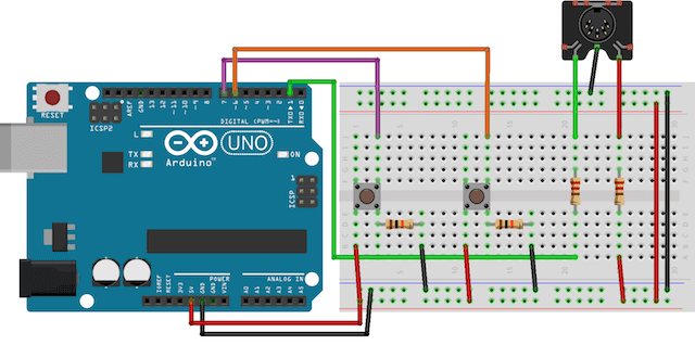
Before starting I leave you a picture where you can see the pins of your MIDI cable, in this way we can correctly identify the pins and especially where to connect each one. Broadly speaking, all you have to do at this point is connect pin 5 of the cable to a 220 ohm resistor and from there to the Arduino Transmit 1, pin 4 to a 220 ohm resistor and from there to the 5V socket of Arduino while pin 2 must be connected to the Ground connection of your controller.
Once this step is done, you do not have a detailed diagram in the photo that is located just below these lines, it is time to connect the buttons. The idea in this section is to achieve, using the digitalRead pin (capable of detecting when the voltage that reaches it changes) to be able to use a transistor to achieve, with the press of a button. For this we only have to use a button so that, the left side of it we connect it to 5V, the right side to a resistance of 220 ohms and from there to ground while, in turn, we also connect the right side to pin 6. The second button would be installed in the same way although, as you can see in the diagram, instead of pin 6 we connect it to 7.
Software to use for home midi controller
Once we have finished with all the hardware, it is time to connect our instrument and test. Before that we need to have a USB-MIDI interface and a MIDI cable to connect the board, which is sending data, with our computer. To achieve this, we have opted for the MIDI v4.2 library created by the guys from Forty Seven Effects that we must have installed on our Arduino and included in the project.
In the case of the computer, we will need a program that is capable of supervising all the MIDI data that arrives at it from Arduino. For this we have different possibilities such as MIDI Monitor (OS X), MIDI-OX (Windows) or Kmidimon (Linux)
To do a little test we just have to connect the Arduino to our computer and execute the following code:
#include
#include
#include
#include
#include

MIDI_CREATE_INSTANCE(HardwareSerial,Serial, midiOut); // crear objeto de salida MIDI llamado midiOut

void setup() {
Serial.begin(31250); // configuracion de serial para MIDI
}

void loop() {
midiOut.sendControlChange(56,127,1); // envío de señal MIDI CC -- 56 = nota, 127 = velocidad, 1 = canal
delay(1000); // retraso
midiOut.sendProgramChange(12,1); // envío de una señal MIDI PC -- 12 = valor, 1 = canal
delay(1000); // retraso de 1 segundo
}
If everything has gone well, you can go to the button test, in case this test has not worked for you you must make sure that all the connections are correct, the circuit is exactly the same as the previous diagram, the circuit is connected to a USB-MIDI interface with a MIDI cable, the MIDI port cables are correctly connected, the MIDI cable is connected to the input of the USB-MIDI interface, the Arduino board is correctly connected to the electrical network and has enough power ...
Testing that the buttons work correctly
Before continuing to feed our program with new functionalities and code that we can get lost in, it is worth stopping for a moment and test that the buttons work properly. For them we have to load the following code:
const int boton1 = 6; // asignacion del boton a una variable
const int boton2 = 7; // asignacion del boton a una variable

void setup() {
Serial.begin(9600); // configuracion del serial
pinMode(boton1,INPUT); // configuracion del boton1 como entrada
pinMode(boton2,INPUT); // configuracion del boton2 como entrada
}

void loop() {

if(digitalRead(boton1) == HIGH) { // prueba de estado del boton1
delay(10); // retraso
if(digitalRead(boton1) == HIGH) { // prueba de estado de nuevo
Serial.println("Boton 1 funciona correctamente!"); // log
delay(250);
}
}

if(digitalRead(boton2) == HIGH) { // prueba de boton 2
delay(10); // retraso
if(digitalRead(boton2) == HIGH) { // prueba de estado de nuevo
Serial.println("Boton 2 funciona correctamente!"); // log
delay(250);
}
}

}
This code just has to be compiled and executed so that, with the USB cable connected, the program tells us if any of the buttons have been pressed.
We create our homemade MIDI controller
Once we have run these tests, it is time to assemble our own MIDI controller for that, you will only have to compile the following code:
#include
#include
#include
#include
#include

const int boton1 = 6; // asignamos boton a la variable
const int boton2 = 7; // asignamos boton a la variable

MIDI_CREATE_INSTANCE(HardwareSerial,Serial, midiOut); // create a MIDI object called midiOut

void setup() {
pinMode(boton1,INPUT); // configuracion del boton1 como una entrada
pinMode(boton2,INPUT); // configuracion del boton2 como una entrada
Serial.begin(31250); // configuracion MIDI de salida
}

void loop() {
if(digitalRead(buttonOne) == HIGH) { // comprobacion de estado
delay(10); // retraso
if(digitalRead(buttonOne) == HIGH) { // comprobacion de estado de nuevo
midiOut.sendControlChange(56,127,1); // envío un MIDI CC -- 56 = nota, 127 = velocidad, 1 = canal
delay(250);
}
}

if(digitalRead(buttonTwo) == HIGH) { // comprobacion de estado
delay(10); // retraso
if(digitalRead(buttonTwo) == HIGH) { // nueva comprobacion de estado
midiOut.sendControlChange(42,127,1); // envío un MIDI CC -- 42 = nota, 127 = velocidad, 1 = canal
delay(250);
}
}
}
As a detail, tell you that you cannot use the Serial.println () command with a MIDI output this time, if you want to show some type of message on the computer, just change:
midiOut.sendControlChange(42,127,1);
per:
midiOut.sendControlChange(value, channel);
where value and channel must have the desired values that you want to display.
Operation example:
Arduino offers you many possibilities to undertake projects on your own https://www.juguetronica.com/arduino . One of the best things is that you can start without being an expert and go on learning, thus motivating yourself to be self-taught.
Greetings.
I am trying to carry out this fantastic tutorial… but the #includes are not complete….
Could you tell me which ones are necessary?
Thank you very much.
Hey.
I would like to make an electronic drum module by replacing the buttons with jack inputs to which a piezoelectric signal will arrive.
Would it be possible to do it?
Please if you could give the includes of this code, I am interested in this project.