If you need to create a project and position it, that is, know how is it placed regarding space, you can use the module MPU6050. That is, this module is an inertial measurement unit or IMU (Inertial Measurment Units) with 6 degrees of freedom (DoF). That's thanks to the 3-axis accelerometer type sensors and a 3-axis gyroscope that it implements to work.
This MPU6050 can know how the containing object is positioned for use in applications navigation, goniometry, stabilization, gesture control, etc. Mobile phones usually include this type of sensors to, for example, control certain functions through gestures, such as stopping if the smartphone is turned over, driving vehicles in video games by turning the mobile as if it were a steering wheel, etc.
What is an accelerometer and a gyroscope?
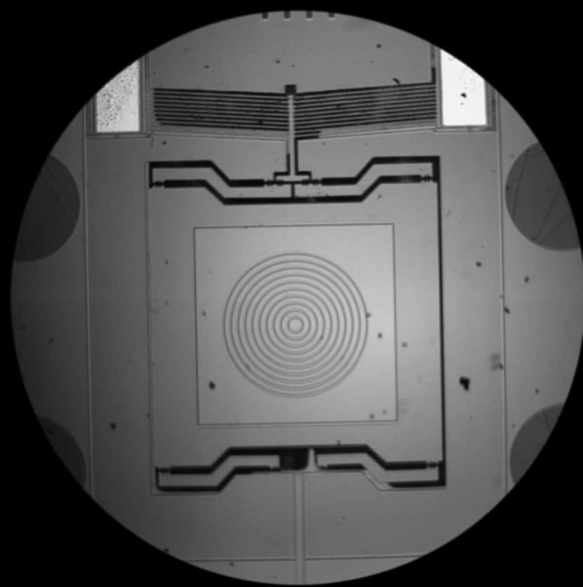
MEMS Examples
Well, let's go in parts. The first thing is to see what these types of sensors are that are able to detect acceleration and turns, as can be deduced from their own names.
- Accelerometer: measures acceleration, that is, the change in speed per unit of time. Remember that in physics, the change of velocity with time (a = dV / dt) is the definition of acceleration. According to Newton's Second Law, we also have that a = F / m, and that is what accelerometers use to work, that is, they use parameters of force and mass of the object. So that this can be implemented in electronics, MEMS (Micro Electro Mechanical Systems) techniques are used, which differ from conventional electronic chip manufacturing techniques, since mechanical parts are created in a MEMS. In this case, tracks or elements capable of measuring accelerations are created. This implies that many other units can be taken, such as velocity (if acceleration is integrated in time), if it is integrated again, we have the displacement, etc. That is to say, very interesting parameters to know the position or detect movement of an object.
- Gyroscope: also called a gyroscope, it is a device that measures the angular velocity of an object, that is, the angular displacement per unit of time or how fast a body rotates around its axis. In this case, MEMS techniques are also used to measure this speed using an effect known as Coriolis. Thanks to this, the angular velocity can be measured or, by integrating the angular velocity with respect to time, the angular displacement can be obtained.
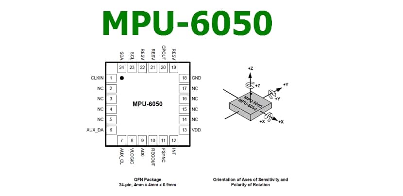
MPU6050 module
Now that you know what the accelerometer and gyroscope are, the MPU6050 module is an electronic board that integrates these two elements to allow you to measure these changes in the position of an element and thus be able to generate a reaction. For example, that when an object moves an LED lights up, or other much more complex things.
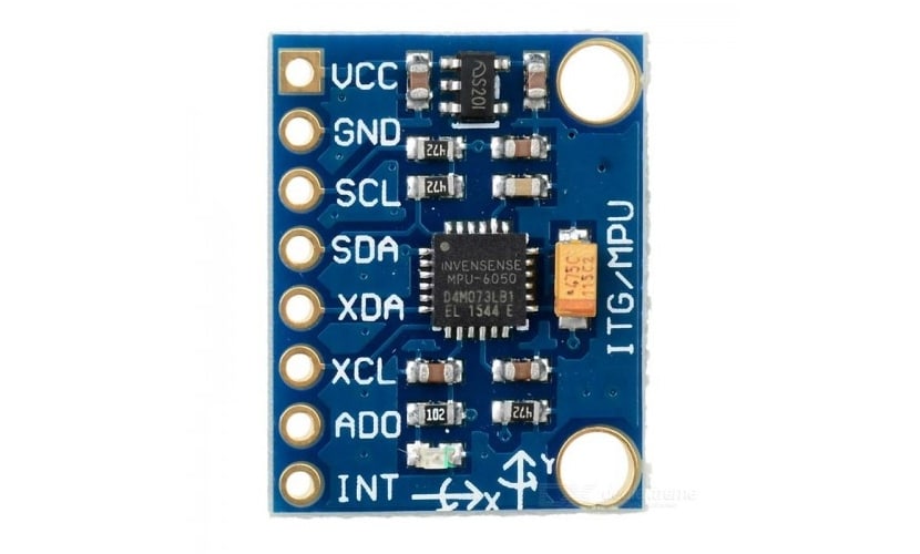
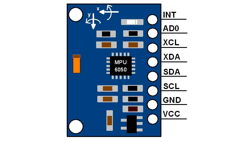
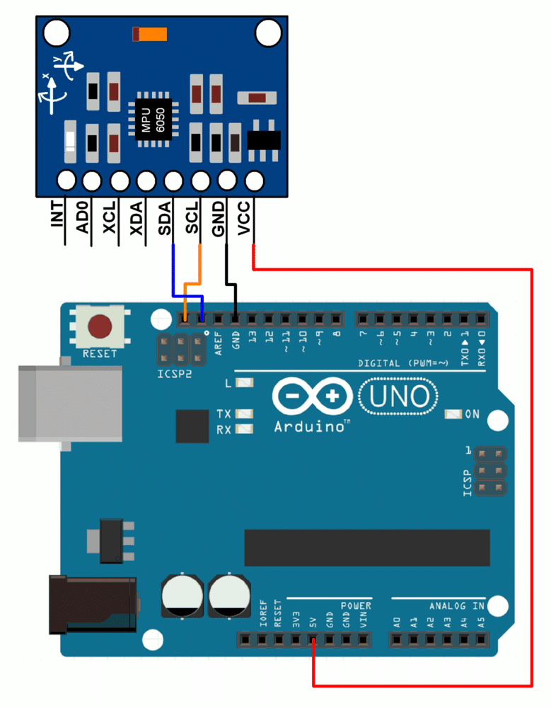
Like I said, it has 6 axes of freedom, DoF, 3-axis X, Y, and Z acceleration accelerometer, and other 3-axis gyroscope to measure angular velocity. You have to take into account not to make mistakes in the way in which you position the module and the direction of rotation for the measurements, since if you make the wrong sign it will be a bit chaotic. Look at the following image where it specifies the direction of the axes (however, notice that the PCB itself also has it printed on one side):
Considering this and the pinout, more or less you have everything clear to start using the MPU6050. As you can see in the previous image, the connections are quite simple and it allows I2C communication to be compatible with most microcontrollers, including the Arduino. The SCL and SDA pins have a pull-up resistor on the board for direct connection to the Arduino board, so you don't have to worry about adding them yourself.
To work with both directions on the I2C bus, you can use these pins and directions:
- AD0 = 1 or High (5v): for I0C address 69x2.
- AD0 = 0 or Low (GND or Nc): for address 0x68 of the I2C bus.
Remember that the operating voltage of the model is 3v3, but luckily it has a built-in regulator, so it can be aliemtned with the Arduino's 5v without problem and it will transform it into 3.3v.
By the way, having an internal resistance to GND, if this pin is not connected, the address by default it will be 0x68, since it will be connected by default to earth, interpreting it as a logical 0.
Integration with Arduino
You can get more information about the I2C bus in this article. You already know that depending on the Arduino board the pins used for the bus vary, but in the Arduino UNO is the analog pin A4 and A5, for SDA (data) and SCL (clock) respectively. They are the only Arduino pins, along with the 5v and GND one to power the board, that you should use. So the connection is as simple as possible.
For the functions of the MPU6050 you can use the libraries of which you can get more information in this link for the I2C of the module and that of the bus MPU6050.
Arduino board programming isn't too straightforward with the MPU6050, so it's not for beginners. In addition, knowing the limits of the accelerations or ranges of the angles, you can calibrate to determine what the exact movement or acceleration has been. However, so that you can at least have an example of how to comment on using it, you can see this code from the Example sketch for your Arduino IDE which will read the values recorded by the accelerometer and gyroscope:
// Bibliotecas necesarias:
#include "I2Cdev.h"
#include "MPU6050.h"
#include "Wire.h"

// Dependiendo del estado de AD0, la dirección puede ser 0x68 o 0x69, para controlar así el esclavo que leerá por el bus I2C
MPU6050 sensor;

// Valores RAW o en crudo leidos del acelerometro y giroscopio en los ejes x,y,z
int ax, ay, az;
int gx, gy, gz;

void setup() {
  Serial.begin(57600);    //Función para iniciar el puerto serie con 57600 baudios
  Wire.begin();           //Inicio para el bus I2C
  sensor.initialize();    //Iniciando del sensor MPU6050

  if (sensor.testConnection()) Serial.println("Sensor iniciado correctamente");
  else Serial.println("Error al iniciar el sensor");
}

void loop() {
  // Leer las aceleraciones y velocidades angulares
  sensor.getAcceleration(&ax, &ay, &az);
  sensor.getRotation(&gx, &gy, &gz);

  // Muestra las lecturas que va registrando separadas por una tabulación
  Serial.print("a[x y z] g[x y z]:\t");
  Serial.print(ax); Serial.print("\t");
  Serial.print(ay); Serial.print("\t");
  Serial.print(az); Serial.print("\t");
  Serial.print(gx); Serial.print("\t");
  Serial.print(gy); Serial.print("\t");
  Serial.println(gz);

  delay(100);
}
If you are a beginner and you do not know well how to program with Arduino IDE, this will be difficult for you to understand, so you can consult our manual with the introductory course to Arduino programming for free ...