Surely you need to create a DIY project using Arduino or any other element and you have to make use of wireless communication. And that happens by having some type of module or device that allows you to transmit using IR, RF, Bluetooth, WiFi, etc. That is, you must be clear about the needs to know what type of signal would be the most appropriate in your case.
In this case we have a guide on the NRF24L01 for you. It is a wireless communication chip that will provide you with what you need to send and receive signals. The type of signals it handles is RF or radio frequency, that is to say, waves of great wavelength, and therefore of low energy, which in the electromagnetic spectrum are between 3 Hz and 300 Ghz in frequency.
What is the NRF24L01?
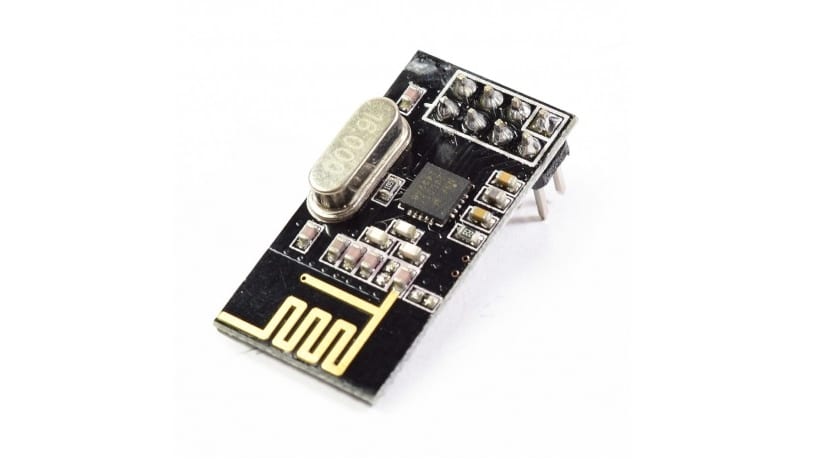
El NRF24L01 is a chip manufactured by Nordic Semiconductor. If it No products found., the chip comes mounted on a small PCB with some auxiliary elements that you need, and therefore composing a module. You can use it in several ways, including connecting it to Adruino as I will show you later.
NRF24L01, as can be deduced from its name, is a wireless communication device that uses RF or radio frequency with the ability to operate at 2,4Ghz - 2,5 Ghz. That is the free band for free use. You already know that other bands are reserved and you have to pay if you want to use them to transmit information. In addition, it integrates a transmitter + a receiver.
Specifically, the frequency band that you can use is from 2.400 Mhz to 2.525Mhz, with the possibility of selecting between 125 channels with 1Mhz spaces between them. However, it is not recommended to use 2.4Ghz frequencies if you are using WiFi networks, drones that work with this frequency, etc., or there will be interference. That is why it is preferable to use from 2.501Mhz onwards.
Regarding its characteristics, works from 1.9 to 3.6v, So it will be easy for you to power it with the Arduino board itself with the 3.3 connection, using batteries, and even with a power supply that has that voltage. In addition, you can configure the transmission speed between 250 Kbps, 1Mbps and up to 2Mbps.
The chip in emissions and receptions can work simultaneously with up to 6 connections of various devices. With that you can be broadcasting or receiving from different points without any problem. And if you are concerned about the robustness or reliability of the communication, the chip itself has logic circuitry to correct data errors and forward information if necessary. Therefore, it frees the processor from this task.
To control it you can use the SPI bus, so its control with Arduino is very simple. In addition, the data pins of the NRF24L01 support up to 5v without problems. Power consumption in Stand By is quite low, so it will not be an element to worry about, and when it is in operation it is not one of the most costly, since it only needs 15mA for sending and receiving data.
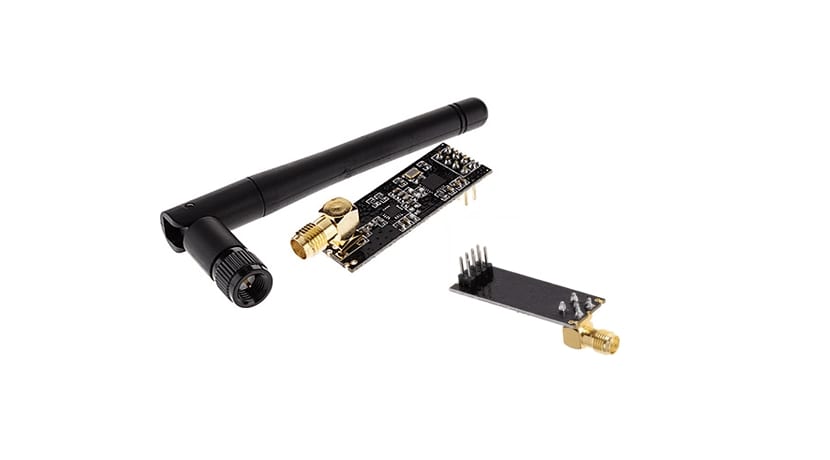
In the market you will find several different modules that mount the NRF24L01 chip, they only change in the auxiliary elements they have or in some details. For example in the type of antenna. Some have an antenna printed on the PCB in a zigzag shape with a range of about 20-30 meters. Others admit a somewhat more powerful external antenna with an amplifier to go from 700 meters to 1 km.
However, the actual scope is limited by some factorssuch as road obstacles, noise or interference from other elements or signals present, transmission speed, supply voltage (higher voltage, greater distance), etc. For example, if you want to transmit at the maximum speed of 2Mbps that will have a great penalty in the distance, which will be only 2 or 3 meters maximum. At lower speeds you may be able to climb that distance.

What do you need to know before buying it?
El NRF24L01 is a very cheap chip that can be used in a multitude of projects. For example, if you do not have an external antenna, you can buy it for up to € 0.65, the external antenna model being a bit more expensive than this one but it is still very cheap and does not usually exceed € 1.7.
If you do not have another emission or reception element, you already know that you must buy two NRF24L01 modules, one to use on one side and the other on the other side of where you want to transmit. They will both act like sender or receiver as you like.
Pinout and mounting of the NRF24L01
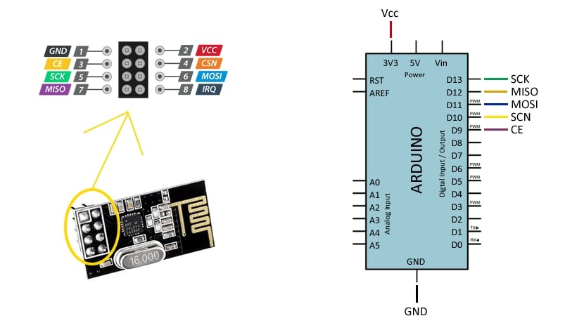
As for the assembly, it is quite simple. The NRF24L01 has 8 pins, therefore its pinout is very easy to understand how you can see in this image that I leave you. On the right you can see the pin diagram of a board Arduino UNO and how each of the module's pins would be connected to it.
As you can deduce, the plate NRF24L01 is powered using the GND and 3.3v pins from Arduino. Remember not to do it with the 5v signal or you will damage the module.
Integration with Arduino
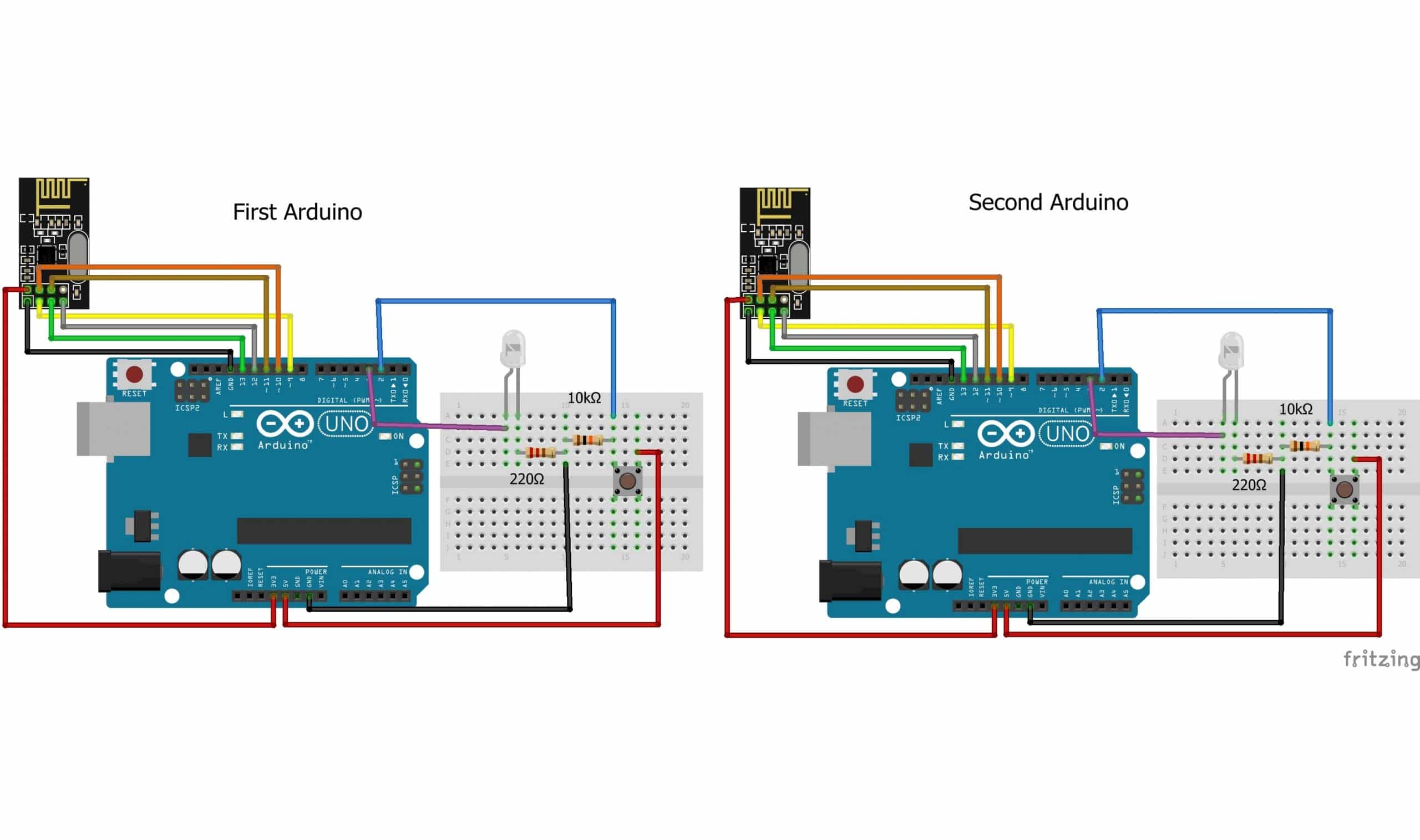
Once you know what the NRF24L01 is and how it can be connected and powered, in addition to the number of projects you can do with a couple of these cheap devices, the next thing is to show a programming example so you can start experimenting with your Arduino IDE. Remember that the data format that you can transmit can be modified in the source code.
You can choose to send and receive a string, an integer, a floating point data, etc. I recommend you our guide on Arduino programming if you are starting. With it you can create your first projects. And as a concrete example for the NRF24L01, here I leave you the codes needed for a string.
Code that you must write in the Arduino IDE and program the Arduino board connected to the NRF24L01 that you are going to assign as transmitter:
#include <nRF24L01.h>
#include <RF24.h>
#include <RF24_config.h>
#include <SPI.h>

const int pinCE = 9;
const int pinCSN = 10;
RF24 radio(pinCE, pinCSN);

// Single radio pipe address for the 2 nodes to communicate.
const uint64_t pipe = 0xE8E8F0F0E1LL;

char data[16]="Aquí tu mensaje" ;

void setup(void)
{
   radio.begin();
   radio.openWritingPipe(pipe);
}

void loop(void)
{
   radio.write(data, sizeof data);
   delay(1000);
}
Here the code that you have to enter in the Arduino IDE and record on the board that you have connected to the dedicated NRF24L01 as receiver:
#include <nRF24L01.h>
#include <RF24.h>
#include <RF24_config.h>
#include <SPI.h>
const int pinCE = 9;
const int pinCSN = 10;
RF24 radio (pinCE, pinCSN);
// Single radio pipe address for the 2 nodes to communicate.
const uint64_t pipe = 0xE8E8F0F0E1LL;
char data [16];
void setup (void)
{
Serial.begin (9600);
radio.begin ();
radio.openReadingPipe (1, pipe);
radio.startListening ();
}
void loop (void)
{
if (radio.available ())
{
int done = radio.read (data, sizeof data);
Serial.println (data);
}
}
With that you will have everything you need and you can try to send words or text strings of one and see how the other receives them. Use two computers connected by USB to the Arduino board to use the console as a means to view the data. Separate them a prudent distance according to the module you have or the configuration you have given it and you will begin to see on the screen of the other computer the characters you have entered in the first code ...
Hello Isaac
I want to complete a project with arduino, rasberry or something else.
Can you give an email contact to explain?
A mine - a01b02@abv.bg
Thank you