
If you want to learn more about him operational amplifier, or if you still do not know what it is, here you can understand a little more this type of device. Furthermore, these Electronic components they are quite used in a multitude of circuits, since they are very practical for a multitude of applications.
Thanks to them, analog signals can be processed, multitude of operations with them, make comparisons, etc. Today they are present in many of the circuits you use every day, including your board. Arduino...
What is an operational amplifier?

El op amp concept would appear in 1947. The first were built using vacuum tubes to be used in the first analog computers. Thanks to them, fundamental mathematical operations could be carried out, such as addition, subtraction, multiplication, division, derivation, integration, etc. Hence they are called "operational" amplifiers ...
Until 1964, thanks to the famous fairchild semiconductor, the first monolithic operational amplifier built on an integrated circuit would not arrive, as they are distributed today. It was the work of engineer Robert John Widlar, and was marked μA702. From there it would evolve to the 741 μA1968, a bipolar chip that has become an industry standard.
These operational amplifiers (also known as Op Amp), are devices capable of performing a multitude of tasks depending on the placement of the accompanying electronic components. Those elements will be attached to its 5 pins (pinout):
- - input: is the inverting input.
- + entry: is the direct entry, that is, the non-investor.
- output: exit.
- + Vss: it is the positive feeding.
- -vss: is negative feeding.
In these devices some very particular conditions that you should know. For example:
- There is no current entering / leaving the inverting and non-inverting pins because the impedance between the two is infinite (in an ideal op amp).
- The differential gain in an ideal one will also be infinite, although in practice it is not possible, since when saturation is reached, the output voltage remains constant.
- The potential difference between the inverting and non-inverting input must be zero.
- Very high gain. But balanced, that is, it will be the same in both inputs. This implies that the output is zero if both inputs are fed by equal signals and of equal polarity
- Very high input resistance, and very low output resistance.
- Like any other amp, they can reach their saturation point. At that time, the output signal will not continue to increase even if the difference between signals does.
- The bandwidth is also infinite in the ideal case, but in a real case it is not possible. This indicates the frequency range within which a given operational function is kept accurate.
And as its name suggests, an op amp is a device that can boost any type of signal (voltage or intensity), both alternating current and direct current. And that is enough to carry out a multitude of operations according to the configurations or modes that we will see in the next section ...
Operating modes
The nice thing about the op amp is that it can be configured in various ways so you can work differently:
Converter
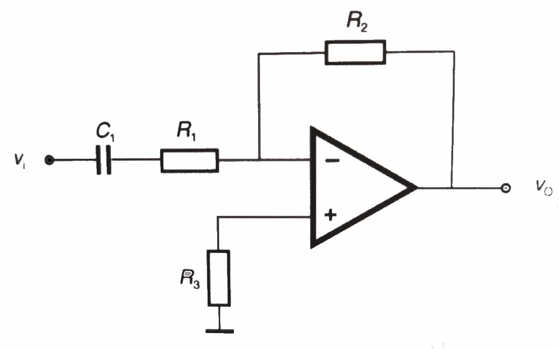
An op amp can work as a voltage amplifier investor and not an investor. When you do it as an inverter, the output voltage is in phase opposition to the input voltage (instead of the same phase as in non-inverters).
Also, you should know that they can work both with corrients continuous as with alternating current in this type of configuration. In the case of AC, a capacitor C1 will be included in series and just in front of R1.
In this case, the greed can be calculated with the formula:
Av = - R2 / R1
While you can also calculate resistance which connects to the input and to ground with:
R3 = R1 R2 / R1 + R2
Not investor
An operational amplifier not investor it will be powered by the non-inverting input, and the output signal is in phase with that of the input. In this case it can also work in this configuration for DC as AC, adding in the second case two capacitors, a C1 in the direct input, and a C2 in series between R1 and the ground.
In this case, the profit is calculated differently:
Av = R1 + R2 / R1
While third resistance it is still calculated with the same formula as in the inverter ...
Voltage adder
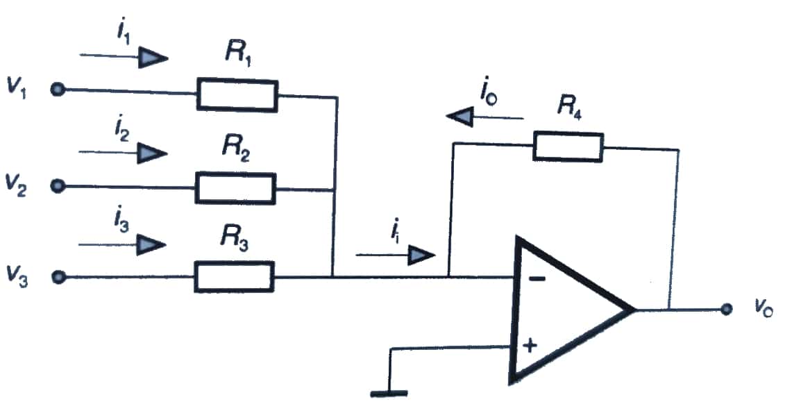
An op amp can be used to mix signals input that come from different sources. This type of circuit uses several inputs (up to a maximum of 10, although there are only 3 in the image).
What happens here is that the amperage is equal to the sum of the partial currents of the inputs (as established by Kirchhoff's law):
Ii = I1 + I2 + I3
Each of these intensities, applying the Ohm's law, will depend of :
I1 = V1 / R1
I2 = V2 / R2
I3 = V3 / R3
Since the input current intensity has the same value and is of the opposite sign to the output current, it can be determined that:
Ii = - Io
Therefore, it can be determined that the output voltage it will be:
Vo = Io R4 = -Ii R4
In this case, again adding capacitors it could also work with AC ...
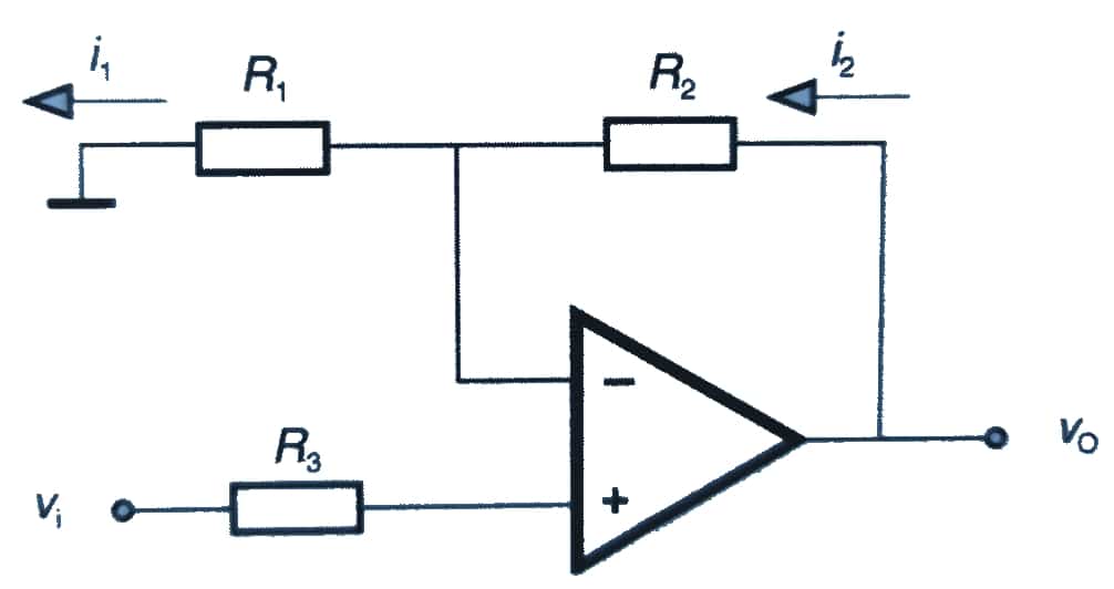
Voltage subtractor
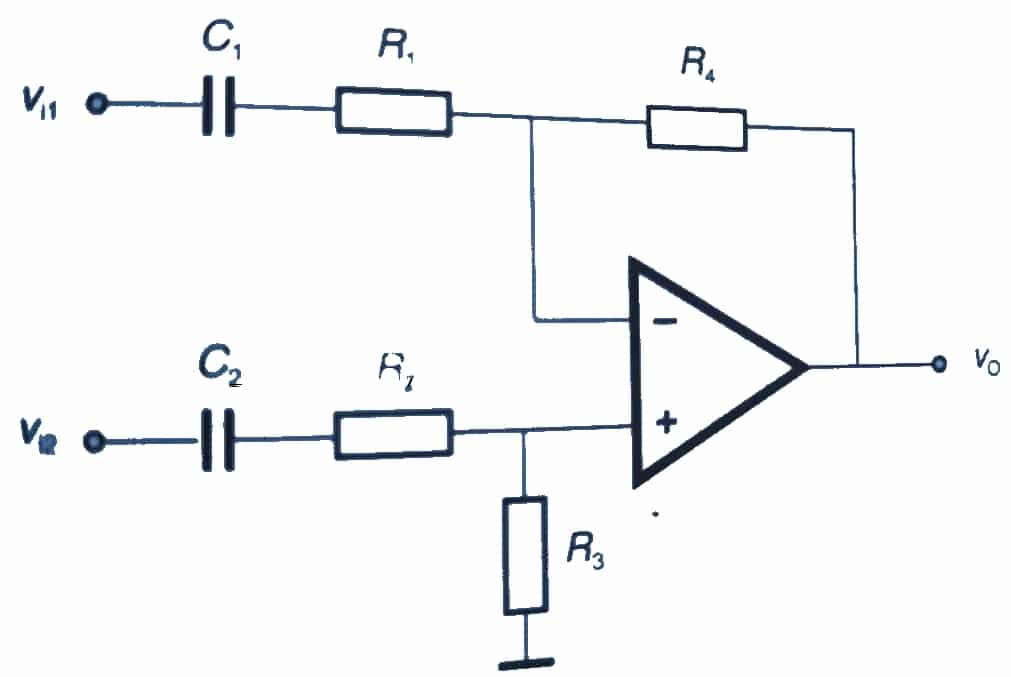
In this case, it is a differential amplifier which is formed by an investor and a non-investor. It can be used to subtract alternating and direct currents, it will be enough to put or remove the capacitors in series with the resistors of their inputs.
In this case, the output voltage it will be:
Vo = Vo1 + Vo2 = R4 / R1 (Vo1 + Vo2)
Comparator

In a configuration like Compare, two quantities of the same type of a signal will be compared and the output signal will indicate whether the values of the inputs are the same or not. That is, the following can occur:
If Vi1 <Vi2 the V outputo it will be positive.
If Vi1 > Vi2 the V outputo it will be negative.
You must bear in mind that if the circuit is used in open loop (without the feedback resistor), it will behave like a voltage comparator.
Other settings
May configure other ways For these operational amplifiers, connect them in cascade, and even replace the resistors with potentiometers to make variable gain amplifiers, as integrator, derivative, as converters, for logarithmic and exponential functions, window comparator, etc. But these are less frequent than the ones I have described above ...
Applications
All the applications of these op amps can be multiple. You must have used them. In fact, they are present in some development boards, in digital calculators, in sound system filters (high pass, low pass, bandwidth, active filters, oscillators), in preamplifiers and audio / video buffers, in regulators, converters, level adapters (eg CMOS-TTL,…), precision rectifiers, to avoid the loading effect, etc.
Su versatility It is because they can function as signal comparators, voltage followers, non-inverting amplifiers, an inverting adder, as an inverting adder, as an integrator, shunt, current-to-voltage converter, for logarithmic or exponential functions, as Digital / Analog converters, etc.
Most used operational amplifiers
If you are a maker or you are doing some kind of DIY project, you will surely want to know some of the most common op amp models. For example:
- μA709M
- LM741
- LM1458
- LM358N
- LM324
- LF353-N
- No products found.
- No products found.
- OP07
- MAX4238
- No products found.
- LM339
- CA 3130
- CA 3140
- TL071
- TL082
- IC747