You've surely heard of the PCF8574 IC, a chip that can be purchased separately or already mounted on a module like many others Electronic components to facilitate your integration with your Arduino board. In this case, it is an extender of the inputs and outputs for the I2C bus.
You may think that Arduino already has its own integrated I2C bus, and it is true. But the PCF8574 can help extend that bus beyond the limits of your development board, which can be of great help to some makers who need more than just what Arduino provides.
What is the I2C bus?
The name I2C comes from Inter-Integrated Circuit or inter-integrated circuits. Its version 1.0 was created in 1992 by Philips. Then a second 2.1 would come in 2000 and today it has become a standard (at 100 kbit / s, although it allows up to 3.4 Mbit / s maximum) when the patent expired in 2006 and can be used freely.
At present it is widely used in the industry for communication, and also very much appreciated by makers for their projects to communicate different microcontrollers and peripherals integrated in one IC.
El I2C is a bus well known from serial communication. It uses a synchronous communication protocol with only 2 channels (there is a third, but it is coupled to reference or GND), in fact it is also known as TWI (Two Wire Interface):
- One for the clock (SCL).
- Other for data (SDA).
That implies that the master and slave they send data over the same cable or track, which is controlled by the first one that is the one that generates the clock signal. Each of the peripheral devices connected to the I2C bus will have a unique address assigned, in order to direct the transmissions. But it is not necessary that the teacher is always the same (multi-teacher), it is always he who initiates the transfer.
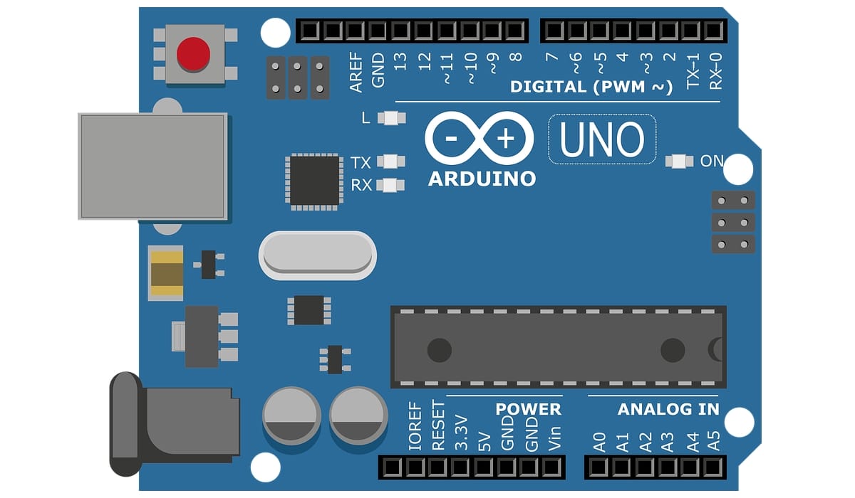
As I already explained in the article on Arduino I2C I referenced earlier, each board has these I2C connections in different places. It is something you have to keep in mind to be able to use it properly in each version of the board:
- Arduino UNO: SDA is in A4 and SCK in A5
- Arduino Nano: the same as the previous.
- Arduino MiniPro: same.
- Arduino Mega: SDA is on pin 20 and SCK on 21.
- More information about plates.
You already know that you can use the I2C for your sketches easily, since the Wire.h library with various functions for this serial communication:
- begin (): start the Wire library and specify if it is master or slave
- requestFrom (): used by the master to request data from the slave.
- beginTransmission (): start transmission with slave.
- endTransmission (): end transmission.
- write ()- Write data from a slave in response to a request from the master, or you can queue a master's transmission.
- available (): will return the number of bytes to read.
- read (): read a byte transmitted from a slave to a master or vice versa.
- onReceive (): Calls a function when a slave receives a transmission from a master.
- onRequest (): Calls a function when a slave requests data from a master.
For more information about Arduino programming and functions you can download our PDF tutorial.
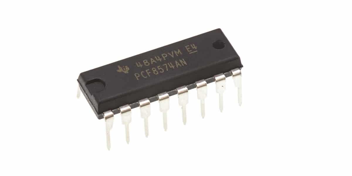
What is the PCF8574?
The PCF8574 is a I2C bus digital inputs and outputs (I / O) expander. It can be manufactured by various manufacturers, in addition to having it available in ICs and modules. In any case, it is very practical to connect it to your Arduino board and have the capacity to control more devices than the motherboard allows.
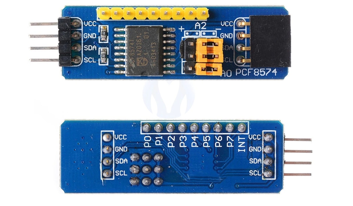
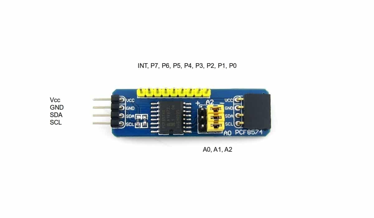
El PCF8574 pinout is simple, since it only includes 8 pins quasidirectional (P0-P7 where the chips to communicate are connected), and on the other hand you have the SDA and SCL that you must connect to the Arduino board, as well as VCC and GND to also power the module. And do not forget the three addressing pins A0, A1, A2 to choose which of the devices the communication is directed to ...
Has Other features what you should know:
- Its connections, being an open drain, can be used both as inputs and outputs.
- La peak current it is 25mA when it acts as an output (sink, when current flows towards PCF8574) and 300 µA (source, current flows from PCF8574).
- La tension power supply is 2.5 and 6v. The stand-by consumption is very low, only 10 µA.
- All departures have latches, to maintain the state without the need for external actions. You only have to act when you want to change the state.
- You can get 8 possible directions, that is, up to 8 devices to communicate with or using 8 modules to expand it up to 64 devices. The addresses (pins A0, A1, A2) will be:
- 000: address 0x20
- 001: address 0x21
- 010: address 0x22
- 011: address 0x23
- 100: address 0x24
- 101: address 0x25
- 110: address 0x26
- 111: address 0x27
- Admits interruption (INT) by a special line to detect data without constantly monitoring.
Integration with Arduino
The connection with Arduino is very simple, you just have to connect Vcc with the 5v pin of the Arduino board, and GND with GND of Arduino. On the other hand, the pins of the PCF8574 SDA and SCL module can be connect with pins 14 (A5 SCL) and 15 (A4 SDA). Only with that it would start to work, obviously you can use the Px to connect the devices you want to communicate ...
Then it would only be missing start with an example sketch in Arduino IDE. You can do it without using an additional library like for example ...
#include <Wire.h>

const int address = 0x38;

void setup()
{
   Wire.begin();
   Serial.begin(9600);
}

void loop()
{
   for (short channel = 0; channel < 8; channel++)
   {
      // Escribir dato en cada uno de los 8 canales
      Wire.beginTransmission(address);
      Wire.write(~(1 << channel));
      Wire.endTransmission();

      // Lee dato del canal
      delay(500);
   }
}
As input:
#include <Wire.h>

const int address = 0x38;

void setup()
{
   Wire.begin();
   Serial.begin(9600);
}

void loop()
{
   short channel = 1;
   byte value = 0;

   // Leer el dato del canal
   Wire.requestFrom(pcfAddress, 1 << channel);
   if (Wire.available())
   {
      value = Wire.read();
   }
   Wire.endTransmission();

   // Mostrar el valor leido por el monitor serie
   Serial.println(value);
}
Or also use libraries, such as the PCF8574 that you can download here and use code similar to this from the example itself that comes along with this library:
#include <Wire.h>
#include "PCF8574.h"

PCF8574 expander;

void setup()
{
  Serial.begin(9600);

  expander.begin(0x20);

  /* Setup some PCF8574 pins for demo */
  expander.pinMode(0, OUTPUT);
  expander.pinMode(1, OUTPUT);
  expander.pinMode(2, OUTPUT);
  expander.pinMode(3, INPUT_PULLUP);

  /* Blink hardware LED for debug */
  digitalWrite(13, HIGH);

  /* Toggle PCF8574 output 0 for demo */
  expander.toggle();

  /* Blink hardware LED for debug */
  digitalWrite(13, LOW);
}


void loop()
{
}