You may be looking for a device that allows you to detect nearby magnetic fields, or to use as a non-contact switch, for applications that need water protection, etc. In that case, you can use Hal effect sensorsThe one of which I will show you everything you need to know to integrate it with your future projects with Arduino. In fact, if you are going to use them together with neodymium magnets, the applications you can get from them are many.
The connection of this type of device is very simple, as you can see. In addition, they are electronic components very cheap and that you can easily find in many specialized stores or online. If you want to know more, you can continue reading ...
The Hall effect
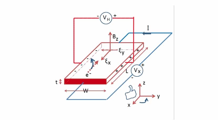
Its name comes from the first discoverer, the American physicist Edwin Herbert Hall. The hall effect It is the physical phenomenon that occurs when an electric field appears due to the separation of electric charges inside a conductor through which a magnetic field circulates. This electric field (Hall field) will have a component perpendicular to the movement of the charges and to the perpendicular component of the applied magnetic field. In this way, among other things, the presence of magnetic fields can be detected.
In other words, when a current flows through a conductor or semiconductor and there is a nearby magnetic field, it is verified that a magnetic force in the load carriers that regroups them within the material. That is, the charge carriers will deflect and cluster on one side of the conductor / semiconductor. As you can imagine, this causes a variation of electric potential in this conductor / semiconductor, producing that electric field perpendicular to the magnetic field.
What is a Hall effect sensor?
Therefore, once you know how the Hall effect works, you can talk about the components or Hall effect sensors that they are able to take advantage of this phenomenon for some practical application. For example, with them you can make measurements of a magnetic field.
These elements are widely used in many electronic projects and frequently used devices. For example, in vehicles you can find them in some security systems, to measure the position of the camshaft in the engine, to measure fluid speeds, detect metals, and a long etc.
The good thing about this type of Hall effect sensors, unlike others, is that they don't need contact. That is, they can do these tasks remotely, in addition to being totally immune to electronic noise, dust, etc., so they are quite durable and reliable in their measurements. However, their range is limited, since they need to be at a certain distance from the generated field in order to be able to capture it.
PREMIUM QUALITY
Within the Hall effect sensors can be found two basic types:
- Analog: they are very basic devices, with a pin or output that will deliver a signal proportional to the intensity of the magnetic field that they are capturing. That is, they are similar to temperature sensor, to the tension, and other sensors that we have detailed in this blog.
- digital: in the case of digital ones, they are much more basic than analog ones. Since they do not deliver an output proportional to the field, but they give a high voltage value if there is a magnetic field and low if there is no magnetic field. That is, they cannot be used to measure magnetic fields like analog ones, simply to detect their presence. Furthermore, these digitals can be divided into two additional subcategories:
- Latch: those of this type are activated when one approaches and maintain their value at the exit until the opposite pole approaches.
- Switch: in these others, the output will not be maintained, they are deactivated when the pole is removed. It is not necessary to bring the opposite pole closer for the output to change ...
I advise you to use neodymium magnets, they are the best for these Hall effect sensors to work well.
If you are looking for an analog type sensor, a good option may be Hall 49E sensor. With it you can detect the presence of magnetic fields, and also measure them. For example, you can measure nearby magnetic fields, make a tachometer using a magnet to measure the revolutions per minute of an axis or speed, detect when a door opens or closes with a magnet, etc. This sensor can be found in several stores for a few cents, or for something else if you want it mounted on a PCB with everything you need in a module ready to use with Arduino:
- No products found.
- No products found.
On the other hand, if what you are looking for is a digital typethen you can buy Hall sensor A3144, which is also a switch type, that is, it will not be necessary to change the pole. This way you will be able to detect the presence of a metallic object, or whether or not there is a magnetic field, and even also create an RPM counter like the previous case. This is also easy to find, and it is as cheap or more than the previous one, both loose and in module:
- No products found.
- Buy module KY-003 with Hall effect A3144
In the case of analog, you must consult the datasheet of the model you have purchased. For example, in 49E You will find a graph of how the magnetic field can be measured and it will help you create the formula that you then have to implement in the Arduino source code to calculate the density of the detected magnetic flux (mT). In the case of the 49E it would be: B = 53.33V-133.3, due to the magnetic range and the voltage that it can deliver at its output ...
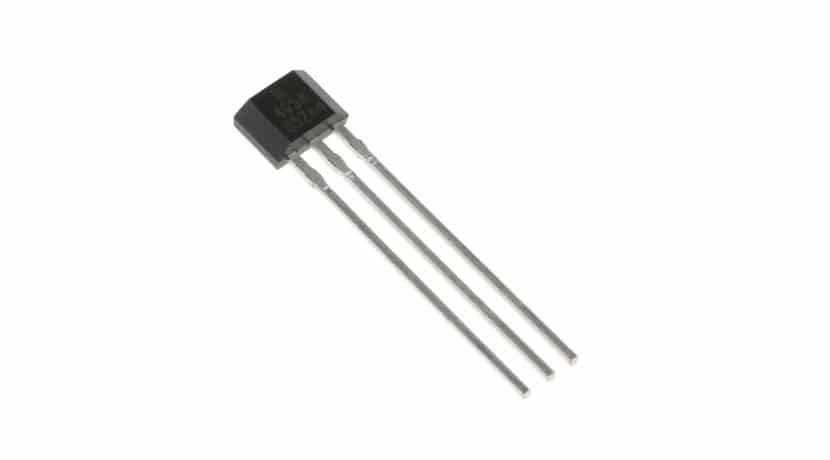
What is common for digital and analog is the number of pins it has (pinout), in both cases it is 3. If you put the Hall sensor with its face facing you, that is, with the face where it has the inscriptions towards you, then the pin on the left will be 1, the central one will be 2 and the one on your right will be 3:
- 1: on both the 49E and the A3144 is the 5V power pin.
- 2: the control unit is connected in both cases to GND or ground.
- 3: in both cases it is the output, that is, the one that measures or detects the magnetic field, generating a voltage through it. Remember that in digital it will take only two values, high or low, while in analog you can apply the previous formula to know how that field is detected ...
Hall effect sensor integration with Arduino
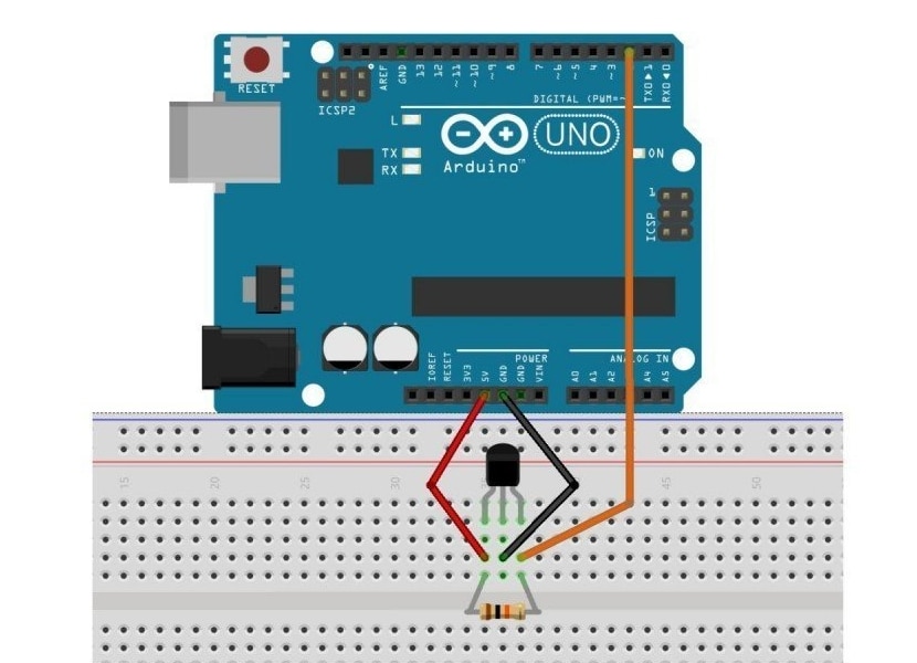
Once you have seen how it works and what you need to know about this Hall effect sensor, with the pinout described, you should already know how it is connect to your Arduino board. In this case, it will connect like this:
- You already know that pin 1 must be connected to the Arduino's 5V voltage output so that it can power it, both in the case of digital and analog.
- The central pin or 2, you have to connect it to GND or ground of your Arduino board.
- In the case of pin 3, it varies depending on whether it is for an analog or digital one:
- Analog: directly connect pin 3 of the Hall sensor to one of the analog inputs of your Arduino board.
- Digital: you must bridge pin 1 and 3 with a pull-up resistor, for example 10K for the circuit to work correctly with the A3144. Other models might need different resistance values ... Once you take that into account, you can connect pin 3 to a digital input on your Arduino board.
It does not matter the number of the input of the board to which you have connected it, just remember the number and then create correctly the source code for your project to work. In this case, there will also be differences between whether you have opted for analog or digital:
- The simple code for the analogical is
const int pinHall = A0;

void setup() {
  pinMode(pinHall, INPUT);
  Serial.begin(9600);
}

void loop() {

  //Filtro para ruido con 10 medidas
  long measure = 0;
  for(int i = 0; i < 10; i++){
      int value =
      measure += analogRead(pinHall);
  }
  measure /= 10;

  //Calcular el voltaje en mV que da la salida del sensor Hall
  float outputV = measure * 5000.0 / 1023;
  Serial.print("Voltaje de salida = ");
  Serial.print(outputV);
  Serial.print(" mV   ");

  //Interpolación a densidad del campo magnético (fórmula)
  float magneticFlux =  outputV * 53.33 - 133.3;
  Serial.print("La densidad del flujo magnético del campo es = ");
  Serial.print(magneticFlux);
  Serial.print(" mT");

  delay(2000);
}
- The simple code for the in digital would:
const int HALLPin = 2;
const int LEDPin = 13;
//El pin 13 en el esquema de nuestro ejemplo no pinta nada, pero se podría agregar un LED a dicho pin para que se encienda si detecta campo magnetico

void setup() {
  pinMode(LEDPin, OUTPUT);
  pinMode(HALLPin, INPUT);
}

void loop() {
  if(digitalRead(HALLPin)==HIGH)
  {
    digitalWrite(LEDPin, HIGH);
  }
  else
  {
    digitalWrite(LEDPin, LOW);
  }
}
I hope this guide has helped you ...