You imagine turn something on or off remotely? You can turn on the heating, or turn it off if you have left it on by mistake, you can also open or close blinds if you have them automatic, or make your house at a suitable temperature by operating on the air conditioning from anywhere. Well, that's what a SONOFF.
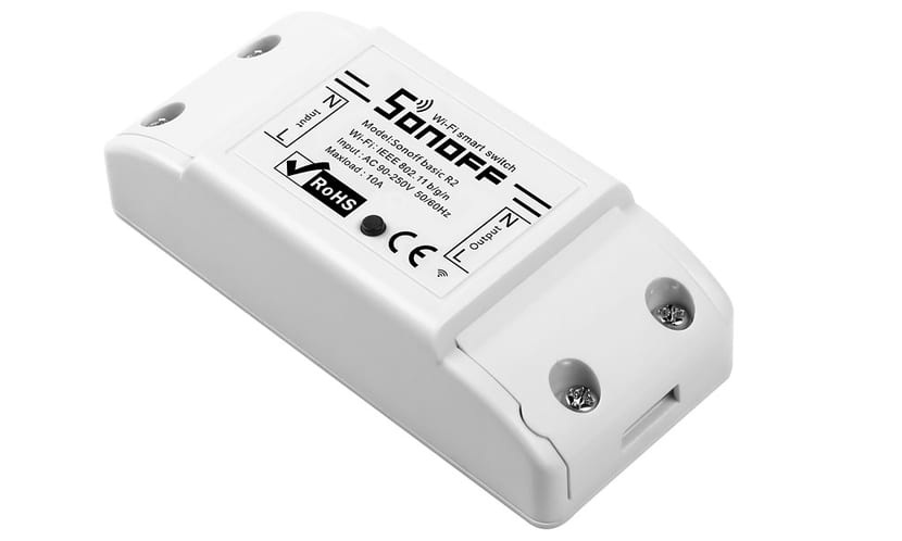
For example, one of the you can find in the market is the Itead Sonoff. It is a device that is based on the ESP8266 module, which will surely sound familiar if you are a maker and create DIY projects with Arduino. It is a very popular WiFi module to which we have already dedicated a special article in Hwlibre. To that module have added a relay to act on the connected devices and thus be able to turn things off or on via WiFi.
What is a sonoff?
Un Sonoff is a WiFi smart switch to be able to remotely turn on and off an electrical appliance. This device allows you to be connected to the Internet through a WiFi router in your home or office. From any device connected to the network and anywhere, you can interact with it to control your devices.
Many commercial sonoffs have your own app for Android or iOS that allow easy control. For example, the Sonoff Basic has the app eWeLink. In addition, in many of these apps they also allow you to configure timers so that they are activated at a specific time. For example, this allows that now on vacations that you will be away from home you can program so that the radio is turned on and off or the blinds are raised and the appearance that the house is occupied to avoid theft ...
Additionally, some commercial Sonoffs implement functions so you can connect them to sensors and that the devices turn on or off depending on the temperature, sound, presence sensor, humidity, etc. This can be useful for a garden irrigation system, to properly air-condition the house, etc. Even some models designed for domotized houses have compatibility with Amazon Alexa / Echo, Google Home, etc.
Other add-ons
In addition to the sonoff, there are other devices that may interest you as a complement, such as WiFi sockets, WiFi bulb sockets, WiFi switches, WiFi-RF gateway, SC-WiFi station, etc., which are perfect complements for your WiFi relay or sonoff.
Make your own Sonoff with Arduino and an ESP8266 module (Easy)
Despite being a very simple and cheap device, you may not always be interested in buying one. If you are a maker and you like to create your own DIY projects, instead of buying the commercial sonoff, you can create it yourself. That would happen by using a relay module for Arduino and a WiFi module. In this way you will have your project connected and ready to operate on the relay that will be in charge of interrupting or connecting the high voltage device.
Another possibility is hack a Sonoff already done to bring new functionalities. For this, the best option you have is the itead sonoff. For example, him No products found., a device from a maker-oriented Chinese company. The device is very well documented and that is why it can be easily hacked to modify it and adapt it to your projects. By being based on an ESP8266 everything will be easier, and it includes its own control app for mobile devices.
Create a simple Sonoff with Arduino
Maybe it will be easier for you create your own Sonoff with Arduino have to modify the firmware of the Itead. Using the Itead and other ready-made devices is very simple, but from just using them to modifying their firmware there is a big difference. So maybe you are interested in a simple way to have a Sonoff created by you.
What do you need?
All what you need for this project it is:
- Arduino UNO, or it would also be worth another plate.
- Breadboard or PCB if you are going to solder.
- ESP8266 module
- Relay module
- Wiring for connections
- PC with Arduino IDE and cable for programming
- Electrical device that you want to control via WiFi
Step-by-step construction
To start build your homemade Sonoff follow this step by step guide:
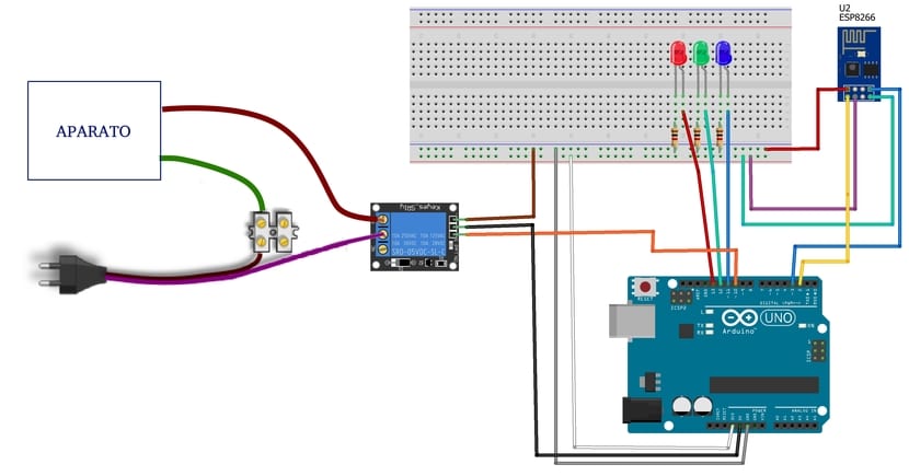
- Once you have all the elements, you must connect the schematic properly as it appears in the picture. Remember that where I have put "Device" is where what you want to control will be connected: stove, fan, TV, light bulb, ... and the plug must power said device. As you can see, what is done is to interrupt one of the conductive wires that go to the device and interpose the relay to act as a switch. If you have questions about the connection, you can consult our manuals:
- Now the following is program in Arduino IDE to get it to work properly. If you are a beginner you can also download the PDF of our programming manual for Arduino. A simple code example to control the relay and the red, green and blue LEDs would be:
#include <SoftwareSerial.h>

#define DEBUG true

SoftwareSerial esp8266(2,3);
void setup()
{
  SSSerial.begin(19200);
  esp8266.begin(19200);

  pinMode(10,OUTPUT);
  digitalWrite(10,LOW);

  pinMode(11,OUTPUT);
  digitalWrite(11,LOW);

  pinMode(12,OUTPUT);
  digitalWrite(12,LOW);

  pinMode(13,OUTPUT);
  digitalWrite(13,LOW);

  sendData("AT+RSTrn",2000,DEBUG);
  sendData("AT+CWMODE=2rn",1000,DEBUG);
  sendData("AT+CIFSRrn",1000,DEBUG);
  sendData("AT+CIPMUX=1rn",1000,DEBUG);
  sendData("AT+CIPSERVER=1,80rn",1000,DEBUG);
}

void loop()
{
  if(esp8266.available())
  {


    if(esp8266.find("+IPD,"))
    {
     delay(1000);
     int connectionId = esp8266.read()-48;

     esp8266.find("pin=");

     int pinNumber = (esp8266.read()-48)*10;
     pinNumber += (esp8266.read()-48);

     digitalWrite(pinNumber, !digitalRead(pinNumber));

     String closeCommand = "AT+CIPCLOSE=";
     closeCommand+=connectionId;
     closeCommand+="rn";

     sendData(closeCommand,1000,DEBUG);
    }
  }
}
String sendData(String command, const int timeout, boolean debug)
{
    String response = "";

    esp8266.print(command);

    long int time = millis();

    while( (time+timeout) > millis())
    {
      while(esp8266.available())
      {

        char c = esp8266.read();
        response+=c;
      }
    }

    if(debug)
    {
      Serial.print(response);
    }

    return response;
}
Once plugged into the Arduino IDE and programmed through the serial port, everything should work fine. Although you can use the serial monitor, you should create a simpler web interface or a small app for iOS or Android. In the case of HTML code It is easier and it would be something like this, that way, from your browser you could manage the on or off of the LEDs and the device connected to the relay:
<html>
<head>
<title>Control con Sonoff</title>
</head>
<body>
<button id="10" class="led">A</button>
<button id="11" class="led">LED AZUL</button>
<button id="12" class="led">LED VERDE</button>
<button id="13" class="led">LED ROJO</button>
<script src="jquery.min.js">
</script>
<script type="text/javascript">
$(document).ready(function(){
$(".led").click(function(){ var p =
$(this).attr('id');
$.get("http://XXX.XXX.X.X:80/", {pin:p});
});
});
</script>
</body>
</html>
You can write it in any text editor, and save it with the name control.html. Remember that for it to work well, you must replace http: //XXX.XXX.XX: 80 with the appropriate IP in your case, that is, the one assigned to the ESP8266 within your WiFi network ... On the other hand, if you want to replace the device label A with the name of the device you are using and make it more intuitive, feel free to do so ...
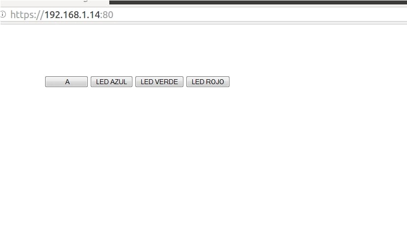
Now if you open this control.html with any web browser can handle your Sonoff. By clicking on the buttons you will see how your circuit works.
Modify the Sonoff firmware (Advanced)
Another operation that you can do, although it is not recommended for most users due to its complexity, is to modify the Itead sonoff firmware. It is possible, but it involves many steps and it is complicated if you don't really know what you are doing. To give you an idea I leave you what you would need and the essential steps, as well as links to the firmware and complete guides in case you dare after reading the essential steps ...
Using ESPurna
What do you need?
To use the Itead Sonoff and program it, you will need the following items:
- Itead Sonoff WiFi Basic
- FTDI or TTL adapter and cable (USB / Serial pins)
- Screwdriver
- Other elements necessary for your project
- A computer for programming
Modify Itead Sonoff WiFi Basic firmware (Basic steps)
To modify the Sonoff of Itead you must acquire one and follow the next steps:
Before handling the device, make sure it is disconnected. It is not advisable to manipulate the relay or circuit when it is connected to the network, since you will be working with AC at 220v and it is not a harmless DC circuit that works at low voltages ...
- Remove the plastic cap from the Sonoff to be able to access the internal circuit. You can use a screwdriver to remove the side covers first and then pry the joint that joins the two parts of the main case until you can remove it.
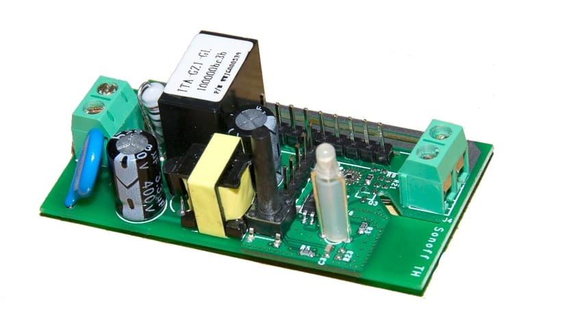
- If you look at the circuit in front of you they can be differentiated very well the parts of the ESP8266 module:
- The electrical elements around the relay are from the AC / DC converter.
- The square black component is the relay that works at 5v (control part) and 220v (output).
- In the center you have some serial connection pins. You can use them to program the microcontroller or to connect more elements. On the GPIO14 you can connect actuators or sensors.
- You will also see a push button next to the pins. You can press it to change the modes you can set.
- The LED that indicates the operation and the mode or state it is in.
- And two green connectors at each end of the PBC. One of them is an input and the other an output. The closest to the relay is the AC input, that is, where the device is connected to the electrical network. The other is the outlet where you can connect the device you want to turn off or on. Remember that it supports up to 10A, that is, a consumption of 2,2kW for 220v.
- Now you will work with the connection pins to load your program. For her you will need the FTDI or TTL, allowing you to connect these pins to a USB on your computer. But beyond connecting it, you must remember that the integrated microcontroller has two modes of operation, a UART mode and another FLASH. The UART mode allows you to load the program and the FLASH to execute it. To go to UART mode to be able to write the program you need to put the GPIO0 (LOW) and GPIO2 (HIGH) pins in certain states. The program will be loaded through the pins marked RX and TX. Of course you will also have to use the 3v3 and GND power pins, as well as the GPIO0 button, the LED or GPIO13 and the relay on the GPIO12.
- Once you have made the connection properly and have your USB cable to connect it to the PC, you can start with the programming itself. Remember that when FTDI you must cross the RX and TX connections, that is, the RX from the Itead to the TX from the FTDI and vice versa.
- Later, it would be a matter of using Arduino IDE to create the necessary code for the control you want to do (you must select the ESP8266 board as the microcontroller device to record). It can also help you firmware developed by Xose Pérez. It's called ESPurna and it is specific to Sonoff WiFi. With its control panel you can control network and security parameters.
- In the end, when you already have it, you can return the pins GPIO0 and GPIO2 to High High states respectively to return to FLASH mode and run your program.
- Once finished, you can make the right connections on your Sonoff to connect the devices you want and give them power. From the app you can control everything ...
More information - Easy programming
Using Tasmota
To do it with Tasmota instead of ESPurna, the generic steps to do so they would be:
- You must first open the case of the Itead Sonoff as in the previous case.
- Then you should solder the wiring or pins to be able to make the power connections and the USB to UART TTL adapter.
- Go to Arduino IDE and in Tools you must select the ESP8266 board instead of Arduino UNO or the one you have by default. You install the new board.
- Now download Tasmota and install it properly to integrate with Arduino IDE.
- Now is the time to program and configure your project as you want and save it to the motherboard ... Once you finish you can connect the components to the sonoff as in the case of ESPurna.
More information - Home automation
The web server does not work, it does not load in the browser.
Hi John,
You mean when you put the IP in your web browser? Have you made sure you have set the correct IP within the local network? The public IP is not valid. It has to be the one assigned to the sonoff. In addition, in the html code you must also replace the X with the appropriate IP.
A greeting!
In fact, I did both, but the moment I load the IP in the browser, it gives me a failed connection. Also when I run the web server, it is not loaded in the form of buttons, but in text.
Hi John,
It works for me correctly, I don't understand why that happens to you ...
I will investigate and if I find the problem I will inform you.
A greeting and thanks for reading
Hello,
I don't understand that with the libraries we have, you use AT codes….
I also don't see you using the ESP8266's WIFI mode which is the focus of this article.
Put a cleaner and clearer example and you will see that the project will understand it.
A greeting.
I forgot,
If what you want is a relay, the ESP8266 controls it by itself, use the Arduino if you want to load the firmware.
Another greeting.
I followed all your steps and it does not work for me, how to know what is the IP that was given to my ESP8266