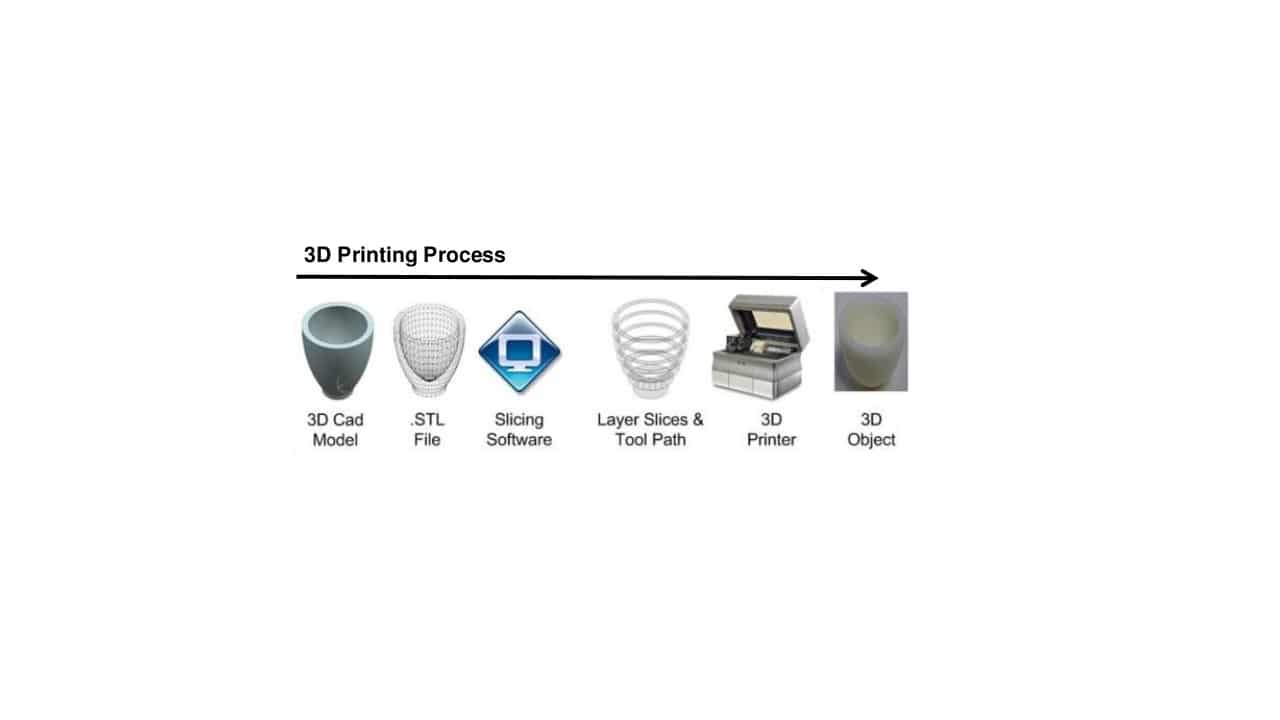
If you have entered the world of 3D printing, surely you have seen the acronym STL in more than one place. These acronyms refer to a type of file format (with extension .stl) which has been very important, although now there are some alternatives. And it is that, 3D designs cannot be printed as is, as you well know, and they need some intermediate steps.
When you have the concept of a 3D model, you must use CAD design software and generate the render. Then it can be exported to an STL format and then passed through a slicer that “slices” it to create, for example, a GCode that is understandable by 3D printer and so that the layers can be created until the piece is completed. But don't worry if you don't fully understand it, here we will explain everything you need to know.
3D model processing
With conventional printers you have a program, such as a PDF reader, or a text editor, a word processor, etc., in which there is a function for printing that, when pressed, the document will go to the print queue for it to be printed. However, in 3D printers it is a bit more complex, since 3 categories of software are needed To make it work:
- 3D modeling software: These can be modeling or CAD tools in which to create the model that you want to print. Some examples are:
- TinkerCAD
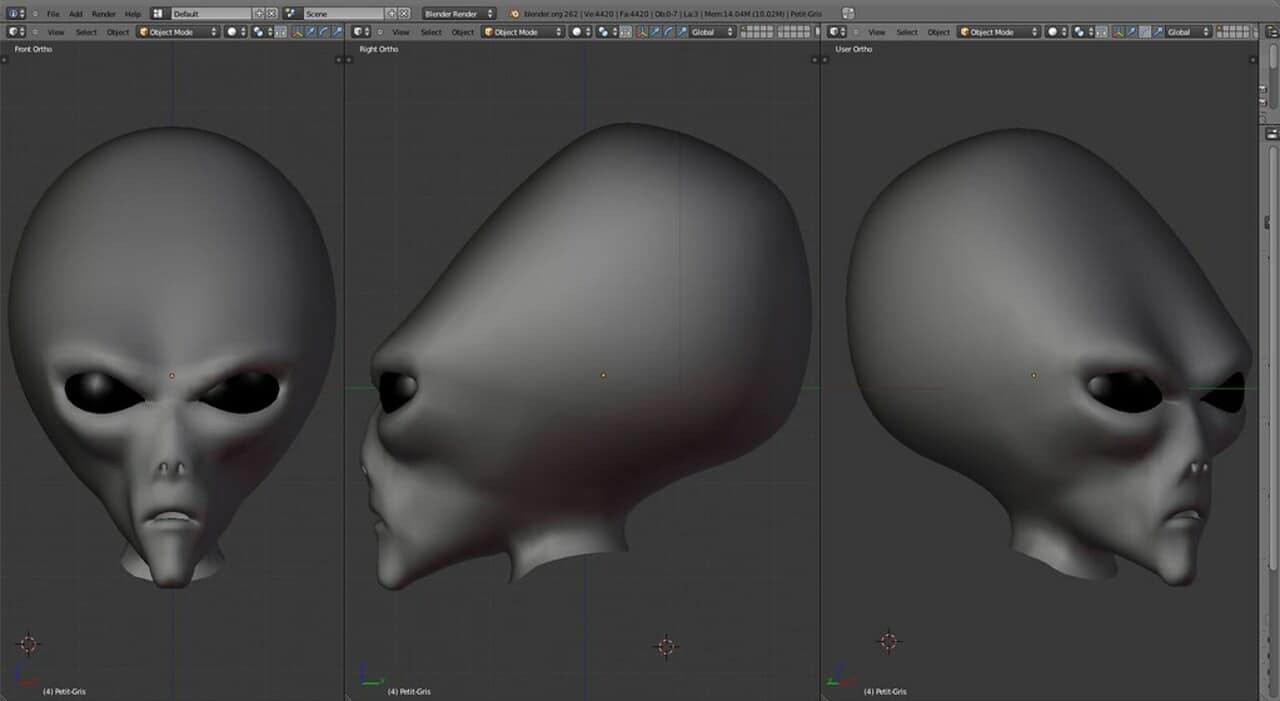
- Blender
- BRL-CAD
- Design Spark Mechanical
- FreeCAD
- openSCAD
- Wings3D
- Autodesk AutoCAD
- Autodesk Fusion 360
- Autodesk Inventor
- 3D Slash
- Sketchup
- 3D MoI
- Rhino3D
- Cinema 4D
- SolidWorks
- Maya
- 3DS Max
- Slicers: it is a type of software that takes the file designed by one of the previous programs and slices it, that is, it cuts it into layers. In this way, it can be understood by the 3D printer, which, as you know, builds it layer by layer, and converts it into G-Code (a predominant language among most 3D printer manufacturers). These files also include additional data such as printing speed, temperature, layer height, if there is multi-extrusion, etc. Basically a CAM tool that generates all the instructions for the printer to be able to make the model. Some examples are:
- Ultimaker Cure
- Repeater
- Simplify3D
- slic3r
- KISSlicer
- ideamaker
- Octo Print
- 3DPrinterOS
- Printer host or host software: in 3D printing it refers to a program whose utility is to receive the GCode file from the slicer and deliver the code to the printer itself, usually through a USB port, or by network. In this way, the printer can interpret this «recipe» of GCode commands with the X (0.00), Y (0.00) and Z (0.00) coordinates to which the head must be moved to create the object and the necessary parameters. In many cases, the host software is integrated into the slicer itself, so they are usually a single program (see examples of Slicers).
These last two points they usually come with the 3D printer itself, like conventional printer drivers. However, design software You will have to choose it separately.
Slicing: what is a 3D slider
In the previous section you have learned more about a slider, that is, the software that cuts the 3D model designed to obtain the necessary layers, its shapes and dimensions so that the 3D printer knows how to create it. However, the slicing process in 3D printing it is quite interesting and a fundamental phase in the process. Therefore, here you can get more information about it.
El step by step slicing process differs slightly depending on the 3D printing technology used. And basically you can distinguish between:
- FDM slicing: In this case, precise control of several axes (X/Y) is needed, since they are moving the head in two axes and greatly require the movement of the print head to build the three-dimensional object. It will also include parameters such as nozzle temperature and cooling. Once the slicer has generated the GCode, the algorithms of the internal printer driver will be in charge of executing the necessary commands.
- SLA slicing: In this case, the commands must also include the exposure times and elevation speeds. And this is because, instead of depositing layers by extrusion, you must direct the light beam to different parts of the resin to solidify it and create layers, while raising the object to allow another new layer to be created. . This technique requires fewer movements than FDM, since only a reflecting mirror is controlled to direct the laser. In addition, something important must be highlighted, and that is that these types of printers do not usually use GCode, but rather they usually have their own proprietary codes (therefore, they need their own cutting or slicer software). However, there are some generics for SLA such as ChiTuBox and FormWare, which are compatible with many 3D printers of this type.
- DLP and MSLA slicing: In this other case, it will be similar to SLA, but with the difference that the only movement required in these will be that of the build plate, which will travel along the Z axis during the process. The other information will be oriented to the exhibition panel or screen.
- Other: For the rest, such as SLS, SLM, EBM, etc., there may be noticeable differences in the printing processes. Keep in mind that, in these three cases mentioned, another variable is also added, such as the injection of the binder and requires a more complex slicing process. And to that we must add that a brand's SLS printer model will not work the same as the competition's SLS printer, so specific cutting software is required (they are usually proprietary programs provided by the manufacturer itself).
Finally, I would like to add that there is a Belgian company called Materialise who has created a complex software that serves in all 3D printing technologies and a powerful driver for 3D printers called magics. Furthermore, this software can be enhanced with modules to generate the appropriate cut file for specific machines.
STL files
Until now, references have been made to the STL files, which are the core of this article. However, this popular format has not yet been studied in depth. In this section you will be able to know it in depth:
What is an STL file?
Format STL-file it is a file with what the 3D printer driver needs, that is, so that the printer hardware can print the desired shape, in other words, it allows to encode the geometry of the surface of a three-dimensional object. It was created by Chuck Hull of 3D Systems in the 80s, and the acronym is not entirely clear.
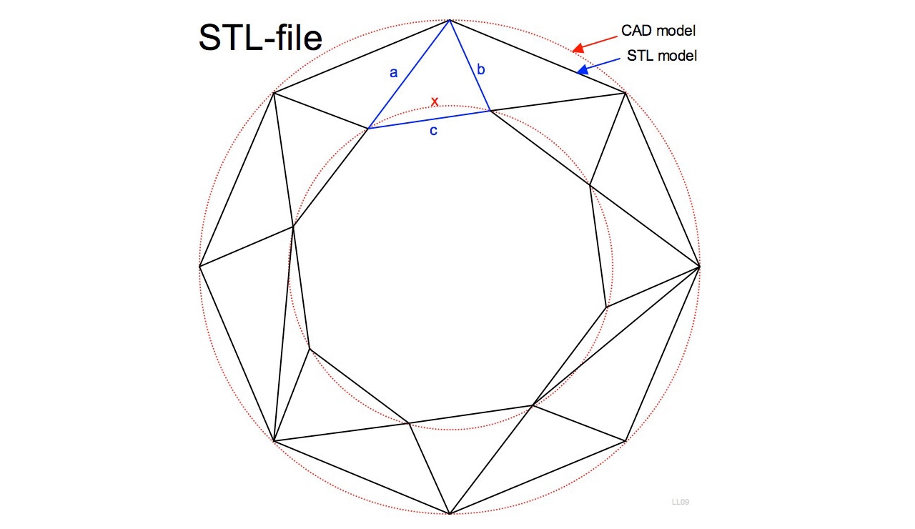
The geometric encoding can be encoded by Tessellation, interposing the geometric shapes in such a way that there are no overlaps or spaces, that is, like a mosaic. For example, shapes can be composed using triangles, as is the case with GPU rendering. A fine mesh composed of triangles will form the entire surface of the 3D model, with the number of triangles and the coordinates of their 3 points.
Binary STL vs ASCII STL
It differentiates between STL in binary format and STL in ASCII format. Two ways to store and represent the information of these tiles and other parameters. A ASCII format example would:
solid <nombre>

facet normal nx ny nz
outer loop
vertex v1x v1y v1z
vertex v2x v2y v2z
vertex v3x v3y v3z
endloop
endfacet

endsolid <nombre>
Where «vertex» will be the necessary points with their respective XYZ coordinates. For example, to create a spherical shape, you can use this example ASCII code.
When a 3D shape is very complex or large, it will mean having many small triangles, even more if the resolution is higher, which will make the triangles smaller to smooth the shapes. That generates huge ASCII STL files. To compact that, we use STL formats binaries, such as:
UINT8[80] – Header                               - 80 bytes o caracteres de cabecera
UINT32 – Nº de triángulos                    - 4 bytes
for each triangle                                        - 50 bytes
REAL32[3] – Normal vector                  - 12 bytes para el plano de la normal
REAL32[3] – Vertex 1                              - 12 bytes para el vector 1
REAL32[3] – Vertex 2                             - 12 bytes para el vector 2
REAL32[3] – Vertex 3                             - 12 bytes para el vector 3
UINT16 – Attribute byte count              - 2-bytes por triángulo (+2-bytes para información adicional en algunos software)
end
If you wish, here you have a STLB file or example binary STL to form a simple cube.
Finally, if you are wondering if is better an ASCII or a binary, the truth is that binaries are always recommended for 3D printing due to their smaller size. However, if you want to inspect the code and debug it manually, then you have no other way to do it than using ASCII and an edit, as it is more intuitive to interpret.
Advantages and disadvantages of the STL
STL files have their advantages and disadvantages, as usual. It is important that you know them to determine if it is the right format for your project or when you should not use it:
- Advantages:
- It's a universal and compatible format with almost all 3D printers, that's why it's so popular against others like VRML, AMF, 3MF, OBJ, etc.
- It has a mature ecosystem, and it is easy to find everything you need on the Internet.
- Disadvantages:
- Limitations on the amount of information you can include, as it cannot be used for colors, facets, or other additional metadata to include copyright or authorship.
- La fidelity is another of its weak points. The resolution is not very good when working with high resolution (micrometer) printers, as the number of triangles needed to describe the curves smoothly would be immense.
Not all STLs are suitable for 3D printing
It seems that any STL file can be used to print in 3D, but the truth is that not all .stl are printable. It is simply a file formatted to contain geometric data. In order for them to be printed they would need to have details of the thicknesses, and other necessary details. In short, the STL guarantees that the model can be seen well on the PC screen, but the geometric figure may not be solid if it were printed as is.
So try verify that the STL (if you have not created it yourself) is valid for 3D printing. That will save you a lot of wasted time and also wasted filament or resin on the wrong model.
Controversy
To finish this point, you should know that there is some controversy over whether to use this file type or not. Although there are still many swarming around, some already consider the STL dead compared to the alternatives. And some of the reasons they give for avoiding the STL for 3D designs are:
- poor resolution since, when triangulating, some quality will be lost compared to the CAD model.
- Color and textures are lost, something that other more current formats already allow.
- No padding control advanced.
- Other files are more productive when editing or reviewing them than an STL in case any rectification is necessary.
Software for .stl
Some Frequently asked questions about the STL file format they are usually referring to how this format can be created, or how it can be opened, and even how it can be modified. Here are these clarifications:
How to open an STL file
If you wonder how open an STL file, you can do it in several ways. One of them is through some online viewers, or also with software installed on your computer. Here are some of the best options:
- Online:
- Windows: Microsoft 3D Viewer
- GNU / Linux: gmsh
- MacOS: Preview or pleasant3d
- iOS / iPadOS: STL SimpleViewer
- Android: Fast STL Viewer
How to create an STL file
For create STL files, you also have a good repertoire of software for all platforms, and even online options such as:
- Online: TinkerCAD, Sketchup, OnShape
- Windows: FreeCAD, blenders, mesh lab
- GNU / Linux: FreeCAD, blenders, mesh lab
- MacOS: FreeCAD, blenders, mesh lab
- iOS / iPadOS: *
- Androids: *
How to edit an STL file
In this case, the software that it is capable of creating also allows edit an STL file, therefore, to see programs, you can see the previous point.
Alternatives
Little by little they have emerged some alternative formats for designs for 3D printing. These other formats are also very important, and include:
- PLY (Polygon File Format): These files have a .ply extension and it is a format for polygons or triangles. It was designed to store three-dimensional data from 3D scanners. This is a simple geometric description of an object, as well as other properties such as color, transparency, surface normals, texture coordinates, etc. And, just like the STL, there is an ASCII and a binary version.
- OBJ: Files with an .obj extension are also geometry definition files. They were developed by Wavefront Technologies for software called Advanced Visualizer. It is currently open source and has been adopted by many 3D graphics programs. It also stores simple geometry information about an object, such as the position of each vertex, texture, normal, etc. By declaring the vertices counterclockwise, you do not need to explicitly declare the normal faces. Also, coordinates in this format do not have units, but they can contain scale information.
- 3MF (3D Manufacturing Format): This format is stored in .3mf files, an open source standard developed by the 3MF Consortium. The geometric data format for additive manufacturing is based on XML. It can include information about the materials, about the color, etc.
- VRML (Virtual Reality Modeling Language): was created by the Web3D Consortium. These files have a format whose objective is to represent interactive three-dimensional scenes or objects, as well as surface color, etc. And they are the basis of X3D (eXtensible 3D Graphics).
- AMF (Additive Manufacturing Format): A file format (.amf) that is also an open source standard for object description for additive manufacturing processes for 3D printing. It is also based on XML, and is compatible with any CAD design software. And it has arrived as the successor to STL, but with improvements such as including native support for colors, materials, patterns and constellations.
- WRL: VRML extension.
What is GCode?
Source: https://www.researchgate.net/figure/An-example-of-the-main-body-in-G-code_fig4_327760995
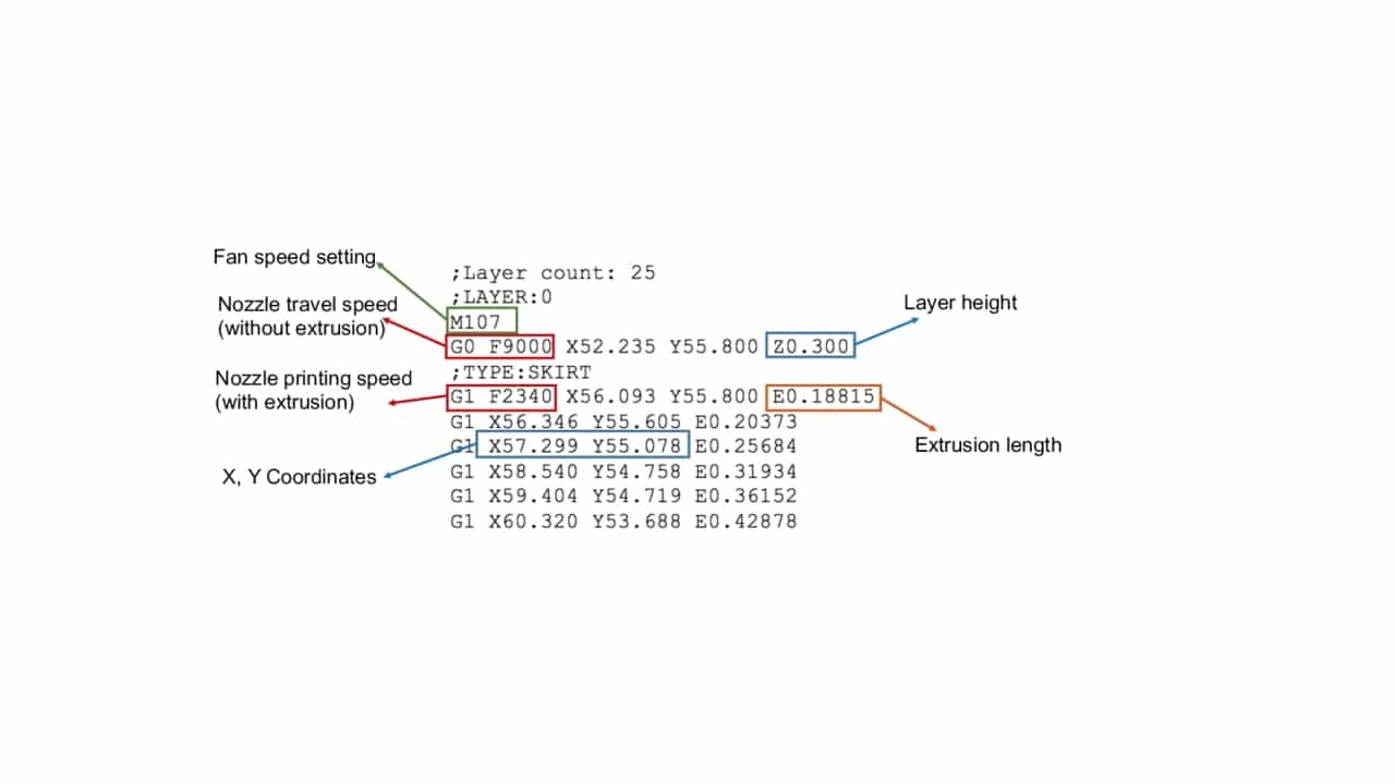
We have talked a lot about the GCode programming language, as it is a key part of the 3D printing process today, moving from STL design to a G-Code which is a file with instructions and control parameters of the 3D printer. A conversion that will be performed automatically by the slicer software.
This code has commands, that tell the printer how and where to extrude the material to get the part, of the type:
- G: These codes are universally understood by all printers that use G codes.
- M: These are specific codes for certain series of 3D printers.
- Others: there are also other native codes of other machines, such as functions F, T, H, etc.
As you can see in the previous image of the example, a series of lines of code which are nothing more than coordinates and other parameters to tell the 3D printer what to do, as if it were a recipe:
- X AND Z: are the coordinates of the three printing axes, that is, what the extruder must move in one direction or another, with the origin coordinates being 0,0,0. For example, if there is a number greater than 0 in the X, it will move to that coordinate in the width direction of the 3D printer. Whereas if there is a number above 0 in the Y, the head will move in the out and in direction of the print zone. Lastly, any value greater than 0 in Z will cause it to scroll to that specified coordinate from bottom to top. That is, with respect to the piece, it can be said that X would be the width, Y the depth or length, and Z the height.
- F: will indicate the speed at which the print head moves indicated in mm/min.
- E: refers to the length of the extrusion in millimeters.
- ;: all the text that is preceded by ; it is a comment and the printer ignores it.
- G28: It is usually executed at the beginning so that the head moves to the stops. If no axes are specified, the printer will move all 3, but if a specific one is specified, it will only apply it to that one.
- G1: It is one of the most popular G commands, since it is the one that orders the 3D printer to deposit material while moving linearly to the marked coordinate (X,Y). For example, the G1 X1.0 Y3.5 F7200 indicates to deposit material along the area marked by the coordinates 1.0 and 3.5, and at a speed of 7200 mm/min, that is, at 120 mm/s.
- G0: does the same as G1, but without extruding material, that is, it moves the head without depositing material, for those movements or areas where nothing should be deposited.
- G92: tells the printer to set the current position of its axes, which is handy when you want to change the location of the axes. Very used right at the beginning of each layer or in the retraction.
- M104: command to heat the extruder. It is used at the beginning. For example, M104 S180 T0 would indicate that the extruder T0 be heated (if there is a double nozzle it would be T0 and T1), while S determines the temperature, in this case 180ºC.
- M109: similar to above, but indicates that the print should wait until the extruder is up to temperature before proceeding with any other commands.
- M140 and M190: similar to the two previous ones, but they do not have a parameter T, since in this case it refers to the temperature of the bed.
Of course, this G-Code works for FDM type printers, since the resin ones will need other parameters, but with this example it is enough for you to understand how it works.
Conversions: STL to…
Finally, another of the things that generates the most doubts among users, given the number of different formats that exist, adding those of 3D CAD designs, and the codes generated by the different slicers, is how to convert from one to another. Here you have some of the most wanted conversions:
- Convert from STL to GCode: It can be converted with slicing software, since it is one of its objectives.
- Go from STL to Solidworks: can be done with Solidworks itself. Open > in file explorer change to format STL (*.stl) > Options > change import as a solid body o solid surface > Accept > browse and click on the STL you want to import > Open > now you can see the open model and the features tree on the left > Imported > FeatureWorks > Recognize Features > and it would be ready.
- Convert an image to STL or JPG/PNG/SVG to STL: You can use online services like Imagetostl, Selva3D, Smoothie-3D, etc, or use some AI tools, and even software like Blender etc, to generate a 3D model from the image and then export to STL.
- Convert from DWG to STL: It is a CAD file, and many CAD design software can be used to do the conversion. For example:
- AutoCAD: Output > Send > Export > enter the file name > select type Lithography (*.stl) > Save.
- SolidWorks: File > Save As > Save As STL > Options > Resolution > Fine > OK > Save.
- From OBJ to STL: Both online conversion services can be used, as well as some local software tools. For example, with Spin3D you can do the following: Add files > Open > choose a destination folder in Save in folder > Select Output format > stl > press the Convert button and wait for the process to finish.
- Go from Sketchup to STL: You can do it with Sketchup itself in an easy way, since it has both import and export functions. In this case you need to export by following the steps when you have the Sketchup file open: File > Export > 3D Model > choose where to save the STL > Save as STereolithography File (.stl) > Export.
More information
- Best Resin 3D Printers
- 3D scanner
- 3D printer spare parts
- Filaments and resin for 3D printers
- Best Industrial 3D Printers
- Best 3D printers for home
- Best cheap 3D printers
- How to choose the best 3D printer
- Types of 3D printers
- 3D Printing Getting Started Guide
Very well explained and very clear.
Thanks for the synthesis.
Thank you very much!