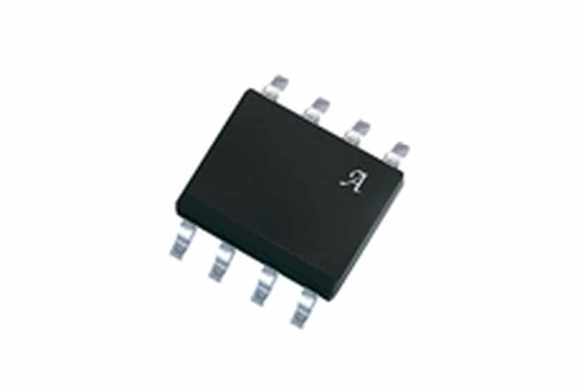
The ACS712 is an economical solution to be able to measure current in your DIY circuits. As a maker, you may need to keep track of the current in a circuit. In this case, you are going to like this component that I present to you. The sensor will detect the amount of current and deliver a voltage output proportional to the current drawn. In addition, since it is already integrated into a module, it makes connection much easier, with connection tabs and everything you need to use it without adding too many extra components.
The applications of this device are many as you will be able to check, even if you have different intensities in the circuit, since you will be able to select the different versions of ACS712 that exist. For example, the ACS712-05A, ACS712-20A, ACS712-30A, etc., for current ranges of 5A, 20A and 30A, respectively.
Hall effect
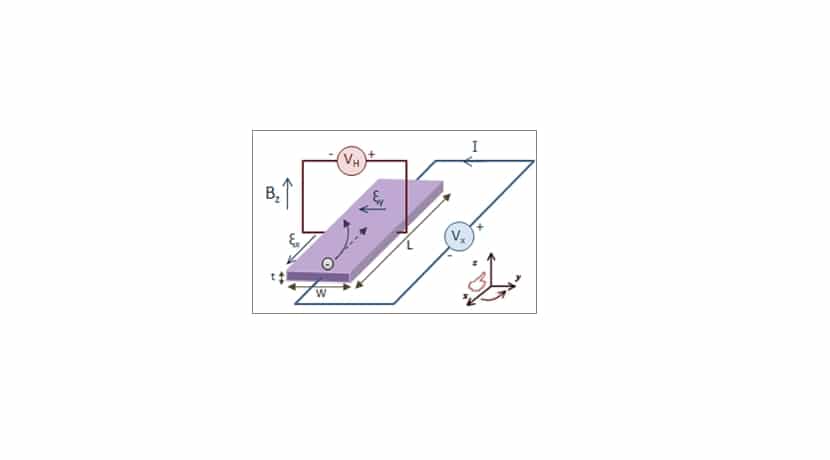
Wikipedia
El ACS712 works thanks to the Hall effect. With it you can measure magnetic fields and currents, as is the case. When a current flows through the Hall sensor, and it approaches a magnetic field flowing vertically to the sensor, then it will create an outgoing voltage proportional to the product of the magnetic field strength and the current. Therefore, knowing the magnetic field, the current value in the conductor or coil can be measured.
All the Hall effect applications They are many, from metal detectors, current measurements, magnetic field measurements, as non-contact signal emitter, metal thickness measurement, etc.
ACS712 Features
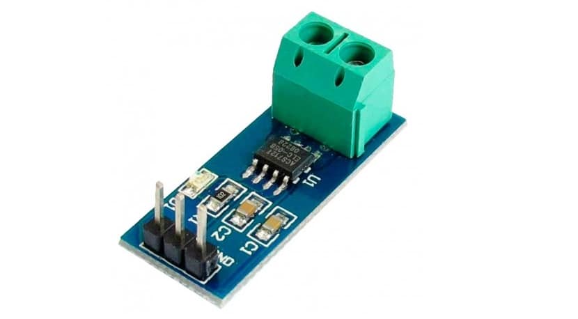
El ACS712 module is very simpleBased on the Hall effect, it has a very simple pinout. On the one hand you see three pins and on the other a connection tab with for two lines from which you want to measure the current intensity of the circuit. The three pins is where the power is connected. As shown in the image above, from left to right, you have Vcc, the output in the middle where it is measured, and the GND furthest to the right.
Depending on the model, you can measure one or another intensity of current in amperes, with three versions Basic ACS712:
- ACS712ELCTR-05B-T: which reaches up to -5 and 5A of maximum tolerated intensity. With a sensitivity of 185mV / A.
- ACS712ELCTR-20A-T: in this case it ranges from -20 to 20A, with a sensitivity of 100mV / A.
- ACS712ELCTR-30A-T: increases to a range of -30 to 30A, with a sensitivity of 66mV / A.
Once you know that, you must bear in mind that at the exit it gives you a voltage or 2.5v voltage if the applied current is 0A. From there, depending on whether it is negative or positive, it will go up or down from that voltage. A straight line can be drawn on a graph by placing voltage and current on the ordinate and abscissa, with the inclination of the slope being the sensitivity of each of these modules.
Therefore, if we know that it is 2.5 volts, you can apply the formula V = SI + 2.5. Where S is the slope that equals the sensitivity. Solving for this to have it as a function of intensity, it can be said that I = V-2.5 / Sensitivity. That is, the voltage minus 2.5 and divided by the sensitivity. You have to take this into account and then calibrate the Arduino microcontroller when you program it.
Pinout, datasheet and where to buy
For your connection to Arduino, it is super simple due to the pinout, just connect the GND pin of your board Arduino UNO with the GND of the ACS712 module, the 5v pin of the Arduino with the Vcc of the module, and the central (output) with one of the Arduino inputs, for example, A0. And with that, the circuit would already be complete, in the absence of connecting the circuit that provides the intensity that you want to measure on the green tab.
Remember that you can get it from different brands, and I advise you see your datasheet to learn more about the particular characteristics that this specific ACS712 module may have, although they are usually quite similar in all manufacturers ... If you want to see an example, here is a Allegro datasheet.
Say also that what you can buy in any specialized store, or in many large online sellers such as Amazon, with prices from € 2 to € 11 depending on the model, such as:
An application example with Arduino
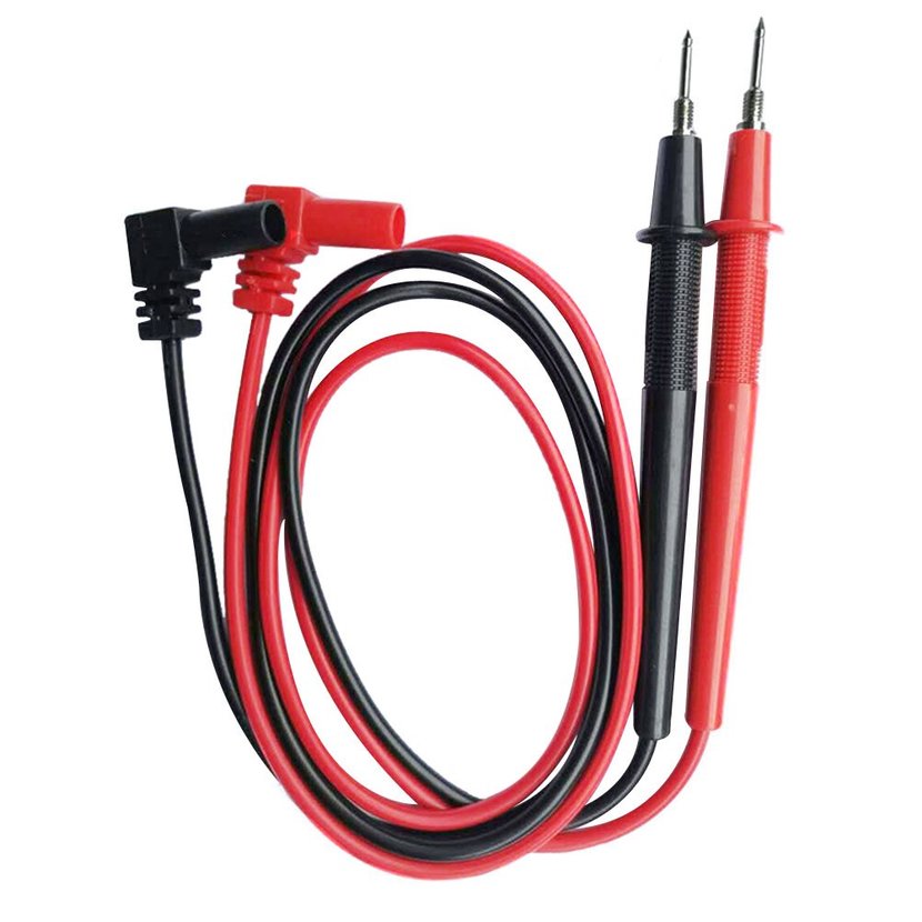
The simplest and most recommended example to start using this element is connect the ACS712 to your Arduino board and then generate a simple code for the Arduino IDE to make current measurements. Install some probes, test leads from a multimeter that no longer works or No products found., and you will have an easy ammeter to touch with the tips some little circuit and determine at what intensity it works. If you do not want to buy or have probes, you can use two cables protected with a good insulation and that resist the intensity you intend to measure.
Take the appropriate precautions, if you work with high intensities use insulating elements or you can suffer serious damage if you suffer an electric shock. Always work with caution ... Look at the characteristics of your module and do not exceed the intensity values for which it is prepared or it will be damaged, nor do you exceed the maximum intensity at which the probes or cables you have chosen can work.
El code for your Arduino IDE sketch It's that simple:
//Ejemplo de código para medir intensidades para un ACS712 de 5A
float Sensibilidad=0.185; //Sensibilidad en Voltios/Amperio para sensor de 5A a 185mV/A

void setup() {

  Serial.begin(9600);
}

void loop() {

  float voltajeSensor= analogRead(A0)*(5.0 / 1023.0); //Para la lectura del sensor
  float I=(voltajeSensor-2.5)/Sensibilidad; //Fórmula para obtener la corriente o intensidad medida con las puntas conectadas al módulo ACS712
  Serial.print("La intensidad en Amperios es de: ");
  Serial.println(I,3);
  delay(200);
}
Considerations
Remember If you have connected the output of the ACS712 module to a different input, you must change the A0 to the appropriate pin. And the same if you have used a module for 20A or 30A, having to modify the value of the declaration of the sensitivity constant to 100 or 66.
You can also modify formulas so that the data returned from measurements is in submultiples of amps, such as mA, if it is more suitable for the utility of your project. You can also modify the delay so that it makes the measurements more consecutively or every longer, as you need to control it. You can even apply filters within the code for measurements, calibrate it, etc.
More things to consider is that if you can know the voltage and current, you could generate formulas In the sketch code to calculate other parameters, such as resistance with Ohm's law, you could also determine the power in watts (w) knowing these parameters, etc. You already know that the limit is your imagination ... well, and the limitations of the technology you use.
You already know that if you want learn more about how to program Arduino, you have a getting started manual in PDF and free to download here.