Un multiplexor is a combinational circuit that has several inputs and a single data output. With this, it is possible to select the passage of only one of its entrances to channel it to its exit. That is, you could select from which input to take the data or bit that is at the input and ignore the rest of the inputs. This is very common in electronics when several connections need to share a single line or bus.
That is, by controlling the multiplexer you can select the appropriate input at all times. What makes it possible that despite having only one connection, you can be working with multiple input devices at the same time without them interfering with each other. Also, you should know that a demultiplexer is generally used in conjunction with the multiplexer in many projects ...
What is a multiplexer?
These combinational services called multiplexers they are not usually complex. They are made up of a few logic gates depending on their number of data inputs and control could increase the complexity. They usually include 2n inputs and a single output, as well as control lines. And you can use several of them in combination to increase that number of available tickets.
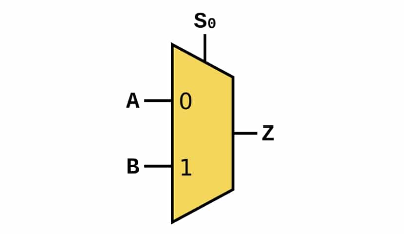
It can be understood as a selector. For example, imagine you have a very simple one with two inputs, the simplest that can be built. That circuit will have a single control input and output. If the inputs are A and B, with the control input you can control if it is A who passes its value to the output S or if it is B who does it. To do this, you only have to vary the value of the control line C. For example, if C = 0 it will be A and if C = 1 it will be B.
As you will understand, if there are more inputs, more will be needed control inputs for selection. In fact, the multiplexer is a special type of decoder, with an enable signal for each included AND gate and an OR gate between the output and the AND gates. That way it can be easily selected.
As for its applications, you can use it for a multitude of things:
- Input selector to share a single bus or line when you have multiple inputs.
- Serializer so that it takes the value of each of its inputs in order.
- For multiplexed transmission using the same connection lines for various data from varied devices. For example, imagine that you want to use the same data pin of a microcontroller to connect several device outputs, but that it can only send information one at a time ...
- Perform logical functions, etc.
Multiplexer types
Depending on the way the transmission is divided, there are various types multiplexers or multiplexing:
- By frequency division
- By time division
- By code division
- By division of wavelength
As you can imagine, they are controlled by frequency, by time by a clock, by binary code, and by wavelength. But here I am only interested in the conventional ...
In addition to the types, as with the demultiplexer, you can find it with more or less channels 2, 4, 8, 16, etc., depending on what you need for your DIY projects.
Differences with a demultiplexer
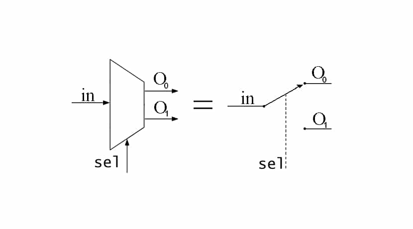
In digital electronics there is demultiplexer, a combinational circuit that is the antagonist of the multiplexer. In this case there will only be one information input, but it can be transmitted through its various outputs. In other words, in this case, the control signals will decide to which output the input data is transferred.
Si you connect a demultiplexer to the output of a multiplexer, you can have a very useful system for learning how both devices work.
Where to buy?

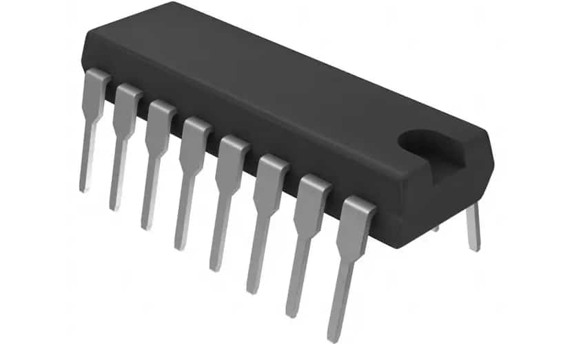
These devices are normally implemented in dip chips very simple. You can find them in a wide variety of brands and with a number of inputs or outputs in case of being a demultiplexer. In addition, they are easily found in various specialized media or online stores. If you are interested in buying one at a good price, these can be good examples to start with your projects:
- IT 8-channel multiplexer
- 8-channel multiplexer perel
- No products found.
- CD74HC4067 16-Channel Multiplexer / Demultiplexer
I advise you to read the datasheets from their manufacturers to get a clear idea of their Pinout, as they may vary depending on the manufacturer or type you have purchased.
cd74hc4067
In addition, as you can see, there are also very good modules that allow you to have both devices in one. It is the case of known CD74HC4067, a small module with TTL technology that can help you to work with its 16 banals in a bidirectional way, by having MUX / DEMUX. That is, you can use it as a kind of smart switch.
Thus, your Arduino can read and write up to 16 different devices with only 5 pins, 4 of them used for control and an additional one to collect the signal that is intended to be read or written according to the selected channel.
The good thing about this chip is that works with both digital and analog signals, so it is compatible with many sensors that work on analog and other digital chips, as well as a multitude of different electronic elements. It gives great versatility. That is why they are also known as I / O expanders or input and output amplifiers ...
You could even use it for communications through the serial port, the I2C bus or the SPI, of which we have already spoken on other occasions.
Of course, before working with him, you must make sure that meet the voltages and currents that admits this circuit so as not to damage it. For example, in this case it can provide up to 20 mA, as well as a voltage of 2 to 6v. However, if you want to work with higher currents you could use a relay or through a transistor.
Integration with Arduino
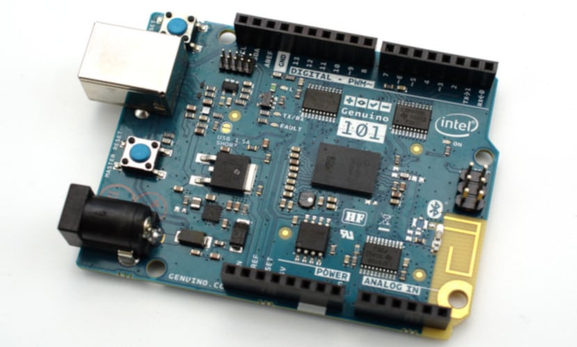
One way of have more inputs on your Arduino board or more outputs, is to use these multiplexers and demultiplexers. With them you will avoid having to buy a higher priced board that has more pins, or having to use other tricks to connect everything you need.
For example, you can use a MUX and DEMUX module to be able to have both in a single element, and then integrate it in a simple way to your project with Arduino. With the CD74HC4067 you can connect it very easily, so you must follow these rules:
- Vcc of the MUX / DEMUX chip you must connect it to Vcc of Arduino or 5V.
- GND, the ground, you must connect it to the GND of the Arduino.
- The pins marked S0, S1, S2, S3 are the ones that control the active channel, with four Arduino digital I / O, such as D8, D9, D10 and D11.
- The EN is also enabling, so that it works as a multiplexer you can connect it to the GND of Arduino.
- And SIG is the output signal that will determine the selected channel. It can be connected to Arduino or to any device that needs to read the output. In this case I have connected it to A0 to obtain the values from the Arduino itself.
- At the other end of the module you will have the inputs in this case, which are C0-C10 that you can connect to your devices.
Once connected, the Arduino code can be simple. The Arduino IDE sketch as multiplexer It can be the following (this code will only turn off and on their channels respectively, but you can modify it to make the project you want):
const int muxSIG = A0;
const int muxS0 = 8;
const int muxS1 = 9;
const int muxS2 = 10;
const int muxS3 = 11;

int SetMuxChannel(byte channel)
{
   digitalWrite(muxS0, bitRead(channel, 0));
   digitalWrite(muxS1, bitRead(channel, 1));
   digitalWrite(muxS2, bitRead(channel, 2));
   digitalWrite(muxS3, bitRead(channel, 3));
}

void setup()
{
   pinMode(muxSIG, OUTPUT);
   pinMode(muxS0, OUTPUT);
   pinMode(muxS1, OUTPUT);
   pinMode(muxS2, OUTPUT);
   pinMode(muxS3, OUTPUT);
}

void loop()
{
   for (byte i = 0; i < 16; i++)
   {
      SetMuxChannel(i);
      digitalWrite(muxSIG, HIGH);
      delay(200);
      digitalWrite(muxSIG, LOW);
      delay(200);
   }
}
If you want to use it as DEMUX, you should only consider that C0-C10 would be the outputs and SIG would be the input. In case you want use it as a demultiplexer, the code would change like this:
onst int muxSIG = A0;
const int muxS0 = 8;
const int muxS1 = 9;
const int muxS2 = 10;
const int muxS3 = 11;

int SetMuxChannel(byte channel)
{
   digitalWrite(muxS0, bitRead(channel, 0));
   digitalWrite(muxS1, bitRead(channel, 1));
   digitalWrite(muxS2, bitRead(channel, 2));
   digitalWrite(muxS3, bitRead(channel, 3));
}

void setup()
{
   Serial.begin(9600);
   pinMode(muxS0, OUTPUT);
   pinMode(muxS1, OUTPUT);
   pinMode(muxS2, OUTPUT);
   pinMode(muxS3, OUTPUT);
}

void loop()
{
   for (byte i = 0; i < 16; i++)
   {
      SetMuxChannel(i);
      byte muxValue = analogRead(muxSIG);

      Serial.print(muxValue);
      Serial.print("\t");
   }
   Serial.println();
   delay(1000);
}
Remember that you can get more information with the help of our free Arduino programming course.
Hello, I am doing a project, the thing as I do to use the 74hc4067 for inputs of 16 infrared obstacle sensors, and that each sensor turns me on a different output. Well, if I could do it with the arduino mega but I need to use 50 infrared sensors and that each one turns on an output, that is, 50 outputs, I am thinking of using several 744067 for sensor inputs and the tlc5940 for outputs, but in what is the programming code I'm a bit lost, thanks in advance for your help.