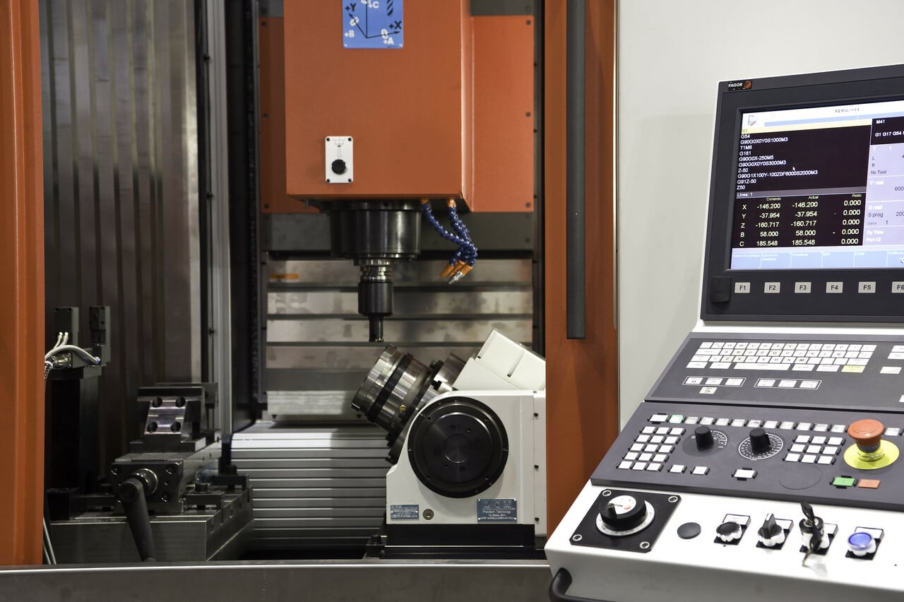
The ubiquitous CNC machines are in a multitude of factories and workshops of all kinds. Their wonderful advantages have made them almost essential machines for machining parts. Now that you know what these types of machines are, the following is know how a CNC machine works, how parts are machined, the programming language they use, as well as the most common applications of these machines.
How a CNC machine works: CNC or numerical control machining
From CAD (Computer-Aided Design or Computer Aided Design) or CAM (Computer-Aided Manufacturing or Computer Aided Manufacturing) designs, some reading or language codes with which the CNC machine will be able to follow the routes or movements marked for the machining of the part in an appropriate order so that the desired result is obtained. That is, so that at the end of the process, the part is identical to the one in the computer design.
In other words, thanks to these codes it will be possible to move the head with the work tool through the axes of the machine. Of course, the tool can be different from one machine to another, some even have a multi-tool head to change between several and offer greater flexibility of work. For example, there may be cutting tools, drilling tools, milling or turning tools, welding tools, locating tools, etc.
Movement control
CNC machines have two or more programmable addresses (axes). Generally there are 3 (X, Y, Z), although sometimes they can have more as we saw in the previous article, in addition to allowing rotations (rotary axes are called A, B, C). Depending on the number of axes, you can perform more or less complex machining. The more axes, the greater degree of freedom of movement, so it could make much more complex carvings.
For control movement Of these axes, two types of systems can be used that can work individually or together:
- Absolute values (code G90): in this case the coordinates of the destination point are referred to the origin point of coordinates. The variables X (measurement of the final diameter) and Z (measurement in a direction parallel to the axis of rotation of the spindle) are used.
- Incremental values (code G91): in this other case the coordinates of the destination point are referred to the current point. The variables U (radial distance) and W (measured in a direction parallel to the axis of rotation of the spindle) are used.
Programmable accessories
Only with a motion control the CNC machine could not be used. Therefore, the machines must be programmed in other ways. The type of CNC machine is, in fact, closely related to the type of programmable accessories it has. For example, within machining you can have specific programmable functions such as:
- automatic tool change: on some multi-tool machining centers. The tool head can be programmed to use the necessary tool in each case without having to put it in the spindle manually.
- Spindle speed and activation: The spindle speed in revolutions per minute (RPM) can also be programmed, including the direction of rotation (clockwise or counterclockwise), as well as stop or activate.
- Refrigerant: Many machining machines that work with hard materials, such as stone or metal, need a coolant so that they do not overheat. The coolant can also be programmed to turn on or off during the duty cycle.
CNC program
CNC machines can be programmed, as has been seen, but they do so by different methods that you should know when operating with one of them:
- Manual: Entering the information you want at a command prompt. To do this, you must know an alphanumeric code that is standardized, such as that of DIN 66024 and DIN 66025.
- Automatic: it is the most usual case at present, and it is carried out by means of a computer connected to the CNC machine. A person will be able to modify the data through software, without needing to know the codes, since the program itself will be in charge of translating them into understandable instructions for the CNC machine. This is done through a language called APT, which in turn will be translated into binary (zeros and ones) so that the CNC machine's microcontroller can understand it and translate it into movements.
Currently, there are also some other CNC machines more advanced and easier to use, like the automatic ones that may need even less human intervention.
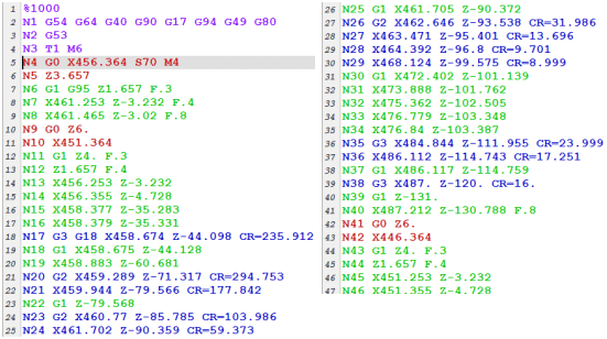
CNC program example. Source: Researchgate
The so-called CNC program, which is written in a low-level language called G and M (standardized by the ISO 6983 y EIA RS274) and composed of:
- G-codes: generic movement instructions. For example, G can move forward, move radially, pause, cycle, and so on.
- M-Codes: that do not correspond to movements or miscellaneous. Examples of M could be starting or stopping the spindle, changing tool, applying coolant, etc.
- N: the program is divided into phases or blocks of instructions that will be headed by the letter N. Each block is numbered, since the machining actions are executed sequentially. The machine will respect the numbering.
- Variables or addresses: The code also contains these types of values, such as F for feedrate, S for spindle speed, T for tool selection, I, J, and K for locating the center of an arc, X, Y, and Z for the movement of axes, etc.
All will depend on the type of machine. For example, a CNC machine for sheet metal bending is not the same as one for cutting. The first does not have a spindle and does not require coolant.

G and M code example table
If you look at the table above, we could use an example block to explain what happens. For example, imagine you have the following code or CNC program:
N3 G01 X12.500 Z32.000 F800
This little snippet of CNC code would be telling the CNC machine, once it is translated into binary, to do the following actions:
- N3 indicates that it is the third block to be executed. Therefore, there would be two previous blocks.
- G01: perform a linear movement.
- X12.500: would move 12.5 mm along the X axis.
- Z32.000: it would move 32 mm along the Z axis. In this case there would be no movement in Y.
- F800: A feed is made at a speed of 800 mm/min.
APT language
On the other hand, the apt language it is a programming language that will be used as an intermediate code between the previous one and the machine code (binary code) understandable by the MCU. It was developed in the MIT laboratory, by Douglas T. Ross. Back then, in 1956, it was used to control servomechanisms, but its use has now spread and it has become an international standard for numerical control.
It was considered a predecessor of CAM, and is similar to other languages such as FORTRAN. This code will be transformed by computer software into a series of binary instructions that will be loaded into the memory of the CNC machine's microcontroller so that it can execute them, generating electrical control signals to move the motors and tools.
This APT language can control many parameters of the CNC machine:
- Spindle speed (RPM)
- Spindle On or Off
- Rotation
- Scheduled stop
- Soft Drink
- Movements in all possible directions (XYZ and ABC)
- Timing
- repeat cycles
- Trajectories
- Etc
Of course, those who operate CNC machines do not need to know this APT language, since the current software is quite intuitive and allows easy control, transparently translating the APT to the user to create the part that has been designed in the CAD/CAM file. However, it never hurts to know that it exists and what it is.
Nowadays, modern CNC machines already have graphical interfaces with touch screens and integrated computer that greatly facilitates its use. They are extremely intuitive, and do not need much learning. Through a pen drive or USB memory, they will allow you to load the design of the piece, so it can be designed on another independent computer.
CNC controller
El cnc-controller It will be the one in charge of interpreting the CNC program, its commands in sequential order, and it will carry out the necessary movements and functions, among other things.
CAM / CAD program
Un CAD or CAM software It will be used to create the design or model of what is intended to be manufactured. The current software already allows to go from this type of formats to a CNC program automatically.
DNC system
As to DNC (Direct Numerical Control), is a term that refers to a computer connected by a network to one or more CNC machines. In this way, the CNC program can be transferred to the machines, either by Ehternet, or by more classic and rudimentary ports such as the RS-232C serial ports, which are still used in many industrial machines.
CNC machine applications
cnc machines they have more applications than you imagine. Much of the industry and workshops, from the smallest to the largest, depend on one or more of these teams. They can even be used at home for certain DIY jobs for makers.
Leisure (DIY and makers)
Many makers have small CNC machines of various types at home to make some DIY projects. It can also be used by individuals to perform certain tasks from home:
- Make jewelry pieces.
- Machining of materials to create parts or components.
- Create parts to repair vehicles or other types of equipment when spare parts are no longer sold.
- Make artistic works or engravings.
Workshops and manufacturing industry
Of course, in the professional sector, both in workshops and factories, it is also very common to see CNC machines, both for carpenters, repair shops, parts manufacturing, the textile industry, the aeronautical sector, decoration, cabinetmaking, etc. For example:
- Sheet metal laser cutting.
- Plasma welding.
- Pick & Place, or to place parts or components right in their assembly place.
- Bending of bars, tubes, plates…
- Drilling.
- Turning or milling of wood.
- Manufacture of custom parts.
- Modeling or additive manufacturing.
- Creation of implants or prostheses for medical use.
- Engravings.
- Etc
electronics industry
Special mention deserves the CNC machines that have also been used in a sector as competitive and advanced as that of electronics and semiconductor industry. These machines can perform a large number of tasks, such as:
- Semiconductor wafer cutting.
- Manufacture of heat sinks from copper or aluminum blocks.
- Creation of casings/structures for computers, televisions, mobiles, etc.
- Pick & Place for placing surface mount components on a PCB board in place for subsequent soldering.
- Welding.
- Laser engraving of brands and logos.
- To shape the lenses.
- Etc
More information
- CNC machines: guide to numerical control
- Prototyping and CNC design
- All types of CNC machines according to use and characteristics
- CNC lathe types and characteristics
- Types of CNC milling machines
- Types of CNC router and CNC cutting
- Types of laser engraving
- Other CNC machines: drilling, Pick & Place, welding and more
- How can a CNC machine help in the company
- Buying Guide: How To Choose The Best CNC Machine
- Maintenance of CNC machines
- Definitive guide on plotters: what is a plotter and what is it for
- The best CNC machines for leisure and professional use
- The best printing plotters
- The best cutting plotters
- The best consumables for potters: cartridges, paper, vinyl, and spare parts